CliveL January 18, 2011, 16:56:00 GMT permalink
Post: 6187329
Originally Posted by
M2Dude
I confess. I'm afraid that I did intentially use that awful pun (sorry
).
Shame on you
Yes, the 188 was welded stainless and as you said, manufacturing was a pain. I didn't work on that aircraft myself, but one reported episode in the flight test programme is worth a digression off topic. Dialogue (maybe that should be monologue) between aircraft and FT control:
t = 0
Godfrey Auty (test pilot): "Mach ... port engine flamed out"
Silence from ground
t = 10secs
G.A.: "Mach .... starboard engine flamed out"
Silence from ground
t= 15 secs
G.A. "Well for Chrissake say something, even if it's only goodbye!"
Luckily the restart drills worked
After those AICU problems the boss came to see me (I was running the S&C section at the time) and said "Your blokes are doing dynamic simulation of aircraft response (on ANALOGUE computers!), do you think they could simulate the 188 intake control system?". To which of course there is only one answer possible, but that is how the two aerodynamicists who did most of the pioneering work on the Concorde AICU came to work together - Derek Morriss from the 188 project and Terry Brown from the S&C group. And boy were we lucky to have that combination
For the record, if my memory serves, the simulation showed that the 188 problem was hysteresis in the mechanical part of the 188 AICU.
M2dude January 18, 2011, 20:53:00 GMT permalink
Post: 6187706
That is amazing Clive, these guys were indeed legend as far as the AICS development went. (And they were doing all that simulation work using analog computers too
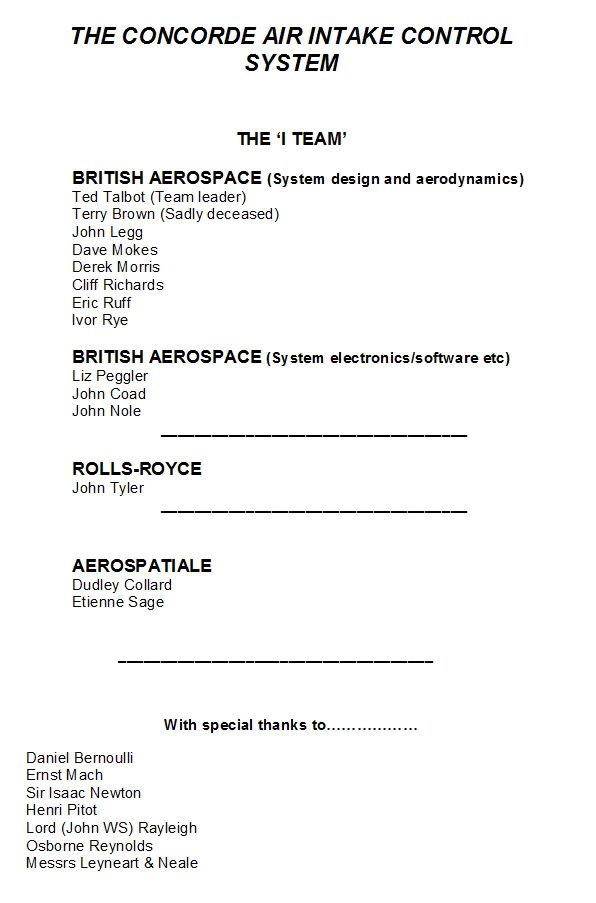
. Here is the one of the 'forward' pages from 'The Concorde Air Intake Control System' publication: (Issue 3 Feb' 2001). There just might be a name or two there that rings a bell.
So much was achieved by such a very small team of people. An achievement that was absolutely pivotal to the successful development of Concorde.
CliveL January 19, 2011, 08:27:00 GMT permalink
Post: 6188447
Here is the one of the 'forward' pages from 'The Concorde Air Intake Control System' publication: (Issue 3 Feb' 2001). There just might be a name or two there that rings a bell.
Yes there are a few bells ringing, although one or two names are phonetically spelt
Etienne would appreciate being called 'Wise' rather than Fage I'm sure!
Never before heard of that publication - how can I get to read copies?
Best regards
CliveL
SubjectsIntakes
Links are to this post in the relevant subject page so that this post can be seen in context.
No recorded likes for this post (could be before pprune supported 'likes').
M2dude January 30, 2011, 09:43:00 GMT permalink
Post: 6212195
Static Ports
CliveL
To further complement the answer, Concorde's static ports are mounted on much bigger plates than usually seen. This is because in supersonic flight the static pressure is peculiarly sensitive to the actual angle of the skin around the 'hole' relative to freestream. Consequently the ports are set in plates that have been machined flat. These plates were then jig-set to accurate angles relative to body datum.
It was found that the relatively miniscule differences in plate alignment produced errors in true Ps measurement and so individual corrections had to be applied to each aircraft. No big deal with a digital ADC of course but not so clever when you are dealing with steam driven analog as we were. (Bearing in mind that any analog ADC is an electro-mechanical device). To give identical Mach 2 cruise readings between ADC 1 & 2 a plug in resistor/diode module was hooked into the respective ADC circuit, and this module stayed with the aircraft always. If we'd ever had to replace a static plate in service (and at BA we never did) we'd have had to have done an in-flight pressure survey in order to calculate the required resistors and altered the module accordingly.
The air intake system, although it used Ps from THREE sources (the side static ports and the static ports built into the nose probe; this being a pressure head and not just a pitot as were the side probes) did not apply any individual aircraft corrections, it just made different corrections between side and nose pressure sources (Ps and Pt). Having a digital processor at it's heart, these corrections were signalled by using 'program pins' at the rear of the AICU rack.
As steam driven as the Concorde ADC was, when it came to RVSM implementation in the late 1990s we found that the air data system was in fact superbly accurate, and no modifications to the computers themselves were required. Such a testament to the original superb design.
I had read about the Compressor lift that cause by the intake shockwave on
XB-70. It help to improve the movement of CP and I think maybe L/D ratio.
I'm know that Concorde has this kind of behavior too (engine shutdown during M2.0) but did they intend to use the compressor lift method in Concorde?
Thanks for all reply.
Best regards
SubjectsEngine ShutdownIntakesShockwave
Links are to this post in the relevant subject page so that this post can be seen in context.
No recorded likes for this post (could be before pprune supported 'likes').
The engine starting sequence was also in airline operation 3-4-2-1. At the gate the altered sequence was 3-2 prior the pushback and 4-1 after due to safety reasons for ground crew and for noise restrictions at some airport stands.
Brit312 explained in post #140:
Yes we always started just the two inboard engines prior to push back and the outers when the push back was complete. This was for a number of reasons, but I do seem to remember it was not unheard of to break the tow bar shear pin on the initial push, so the less power the better
Remember that Concorde had no APU and no across the ship ducting for stating engines, therefore prior to push an air start unit was plugged into each pair of engines and the inboard engines would be started. This allowed, after push back, air from each inboard engine to be used to start it's outboard engine.
The other good reason for starting the inboards prior to push was that with no APU the cabin temp would rise quite quickly [specially in places like Bahrain in summer] and never mind the passengers
comfort, but some of M2dude and ChristiaanJ fancy electronic equipment was very temp sensitive , especially those intake control units down the rear galley. With Two engines running we could use their bleed air to at least try and hold the cabin air temp during the push back
I must admit that I am no expert (not yet
), but it seems both sequences follow the logic to feed the blue hydraulic by engine#3 first, then one of the two yellow systems (2 or 4) and the green hydraulic (engines 1&2) which supplies power to some more services than the blue (droop nose and visor, landing gear, main wheel brakes with anti-skid and nosewheel steering).
Well, I hope, this was not a stupid answer before I took a chance for a nonstupid question
- but I am so exited about this thread and just want a little bit to give back!
Thanks for the probably best thing ever I have found in the internet. Thank you M2dude, Brit312, ChristiaanJ, Exwok, Bellerophon, Landlady et al.!
How many shockwaves does the concorde's inlet produce? I've been told it was like 3 or so, but looking at some diagrams it looks like there are 7... two stronger ones, three weaker ones, a bendy stronger one, a gap and then the terminal shock.
SubjectsIntakesShockwave
Links are to this post in the relevant subject page so that this post can be seen in context.
No recorded likes for this post (could be before pprune supported 'likes').
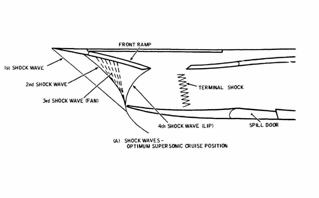
How many shockwaves does the concorde's inlet produce? I've been told it was like 3 or so, but looking at some diagrams it looks like there are 7... two stronger ones, three weaker ones, a bendy stronger one, a gap and then the terminal shock.
OK here we go:
1) The first shock was generated from the top lip of the intake
2) A second shock is generated from the fwd ramp hinge
3) A third isentropic fan shock is generated from the progressively
curved section of the fwd ramp
4) A 4th shock was generated fron the bottom lip
5) A terminal shock system is generated by the coalescence of
still supersonic and now subsonic air at the upper section of the ramp
area.
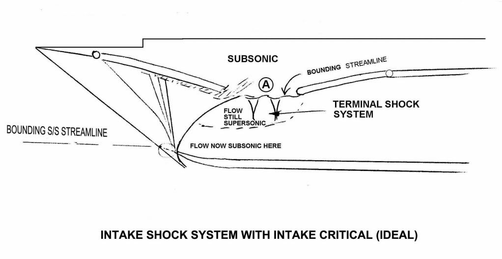
Hopefully these two diagrams will help. The first hand illustration above gives the 'theoretical' shock pattern and the second below gives an illustration of practical flows within the inlet. Both assume critical operation at Mach 2.
I hope all this blurb helps
Best regards
Dude
Last edited by M2dude; 5th April 2011 at
08:35
.
SubjectsIntakesShockwave
Links are to this post in the relevant subject page so that this post can be seen in context.
No recorded likes for this post (could be before pprune supported 'likes').
M2dude gave a good answer on your question in post #1085, so I think I may quote this here again.
Originally Posted by
M2dude
As far as the MAX SPEED bit goes, Concorde was as we know flown to a maximum of Mach 2.23 on A/C 101, but with the production intake and 'final' AICU N1 limiter law, the maximum achievable Mach number in level flight is about Mach 2.13. (Also theoretically, somewhere between Mach 2.2 and 2.3, the front few intake shocks would be 'pushed' back beyond the lower lip, the resulting flow distortion causing multiple severe and surges).
The maximum altitude EVER achieved in testing was I believe by aircraft 102 which achieved 68,000'.
The first bit of the moveable front ramp was carefully shaped to give a sequence of weak shocks that reduced the Mach Number so gradually that shock losses were minimised. This was close to an isentropic process, hence the name. The geometry was arranged so that as the progressive shocks were generated and the Mach angles and shock angles changed the weak shocks tended to 'focus' on a point just ahead of the lower lip. This then became effectively a single 'shock' at that point. Hence isentropic fan shock.
So the lower lip forms a normal shock and the airflow goes subsonic immediately behind it, the supersonic flow above somehow collide and form a shock between the ramps? I understand how the subsonic and supersonic flow coming together would reduce the average velocity -- I'm still surprised the gap between the forward and rear ramps wouldn't act like a divergent surface and cause the supersonic flow to accelerate rather than come down to subsonic speed.
The shock from the lower lip would, on its own, give subsonic flow across the intake, but the change in flow direction where the flow off the solid ramp started to traverse the gap (where Dude's drawing shows the flow going into the void) produced an expansion 'fan' that accelerated the flow in its vicinity and this gave supersonic flow in the upper half of the duct but there was a shear across the height of the duct there. The total
effective
duct area however was convergent back to about the leading edge of the rear ramp, so the Mach Number reduced continually up to that point. Then the 'terminal shock' brought the flow down to below Mach 1 and from there on the divergent subsonic duct did the usual deceleration job. The whole point of the intake geometry was that the purely aerodynamic boundary between main duct and ramp void was infinitely flexible in shape, which made the design very tolerant of flow disturbances.
SubjectsExpansionIntakes
Links are to this post in the relevant subject page so that this post can be seen in context.
No recorded likes for this post (could be before pprune supported 'likes').
The first bit of the moveable front ramp was carefully shaped to give a sequence of weak shocks that reduced the Mach Number so gradually that shock losses were minimised.
Must have been a highly efficient inlet for a Mach 2 plane: Two traditional oblique waves; a fan-shock (also oblique); a shockwave off the lip that is normal and oblique depending on how far you are away from the lip, and a normal terminal shock.
This was close to an isentropic process, hence the name.
So, isentropic would, in this context, mean that no shock-losses occurred at all?
The whole point of the intake geometry was that the purely aerodynamic boundary between main duct and ramp void was infinitely flexible in shape, which made the design very tolerant of flow disturbances.
Makes sense for an airliner that you would design an inlet this way
SubjectsIntakesShockwave
Links are to this post in the relevant subject page so that this post can be seen in context.
No recorded likes for this post (could be before pprune supported 'likes').
Must have been a highly efficient inlet for a Mach 2 plane: Two traditional oblique waves; a fan-shock (also oblique); a shockwave off the lip that is normal and oblique depending on how far you are away from the lip, and a normal terminal shock.
Yes is was very efficient - 94.7% pressure recovery at M 2.0 cruise
So, isentropic would, in this context, mean that no shock-losses occurred at all?
In theory yes, but in practice there was a small loss.
SubjectsIntakesShockwave
Links are to this post in the relevant subject page so that this post can be seen in context.
No recorded likes for this post (could be before pprune supported 'likes').
And a thank you from me CliveL for your superb explanations regarding intake shock structure. It can not be over-emphasised just what an amazing achievement the Concorde engine/intake combo was. I can think of no other design in the world, before or since, civil or military, where a supersonic engine/intake marriage gave such incredidable levels of performance, stability and predictability. I just regard myself as being extremely fortunate to have been able to 'play with' this amazing kit for so many years and see what design excellance really is. (And at least pertly understand it too).
SubjectsIntakes
Links are to this post in the relevant subject page so that this post can be seen in context.
No recorded likes for this post (could be before pprune supported 'likes').
I can think of no other design in the world, before or since, civil or military, where a supersonic engine/intake marriage gave such incredidable levels of performance, stability and predictability.
I think Dude's above statement more or less characterises the Concorde design and therefore this entire thread - which I have read, avidly, since post #1. However, since Dude made the statement most specifically about the synergy of the whole intake, engine and nozzles, it is worth reiterating that Concorde's only real peer in her occupation of the very highest and fastest regimes of wing borne flight - the SR71 - initially at least, had a lethal gene. Asymmetric 'Unstart' caused by intake instability.
Without proper scheduling, disturbances inside the inlet could result
in the shock wave being expelled forward--a phenomenon known as an
"inlet unstart." That causes an instantaneous loss of engine thrust,
explosive banging noises and violent yawing of the aircraft--like
being in a train wreck. Unstarts were not uncommon at that time in
the SR-71's development,
This quote is from a much longer article quoted in this thread, about a test flight by Bill Weaver, a Lockheed development pilot, in which Weaver was, quite literally torn out of the aeroplane at Mach 3.2, as was his back seater who, sadly, did not survive the incident.
Basically, a relatively small failure within the intake/spike structure of the SR71 engine, was enough to simply tear the airframe apart within seconds of onset. The scale of forces within these structures therefore, must be almost beyond imagination and yet the Concorde design was such that she did not suffer such destructive failures.
My admiration for everyone who worked on her is endless.
SubjectsIntakesNozzlesSR-71
Links are to this post in the relevant subject page so that this post can be seen in context.
No recorded likes for this post (could be before pprune supported 'likes').
I can think of no other design in the world, before or since, civil or military, where a supersonic engine/intake marriage gave such incredidable levels of performance, stability and predictability.
Well, the XB-70 had an inlet with an efficiency in the 90% range but it wasn't as stable/predictable (it suffered unstarts).
911slf
I believe that engine #4 was limited to somewhat less than max power until 60kt because of a vibration issue.
What kind of vibration issue occurred?
SubjectsIntakes
Links are to this post in the relevant subject page so that this post can be seen in context.
No recorded likes for this post (could be before pprune supported 'likes').
Jane-DoH
One of the real beauties of the Concorde intake was that it was completely self-startiing, and so unstarts as such were never heard of.
Regarding the vibrations thing, here is my post #80:
The reason that #4 engine was limited to 88% N1 on take-off was an interesting one, down to something known as 'foldover effect'. This was discovered during pre-entry into service trials in 1975, when quite moderate levels of first stage LP compressor vibrations were experienced at take-off, but on #4 engine only. Investigations revealed that the vibrations were as the result of vorticies swirling into #4 intake, in an anti-clockwise direction, coming off the R/H wing leading edge. As the engine rotated clockwise (viewed from the front) these vorticies struck the blades edgewise, in the opposite DOR, thus setting up these vibrations. The vorticies were as a result of this 'foldover effect', where the drooping leading edge of the wing slightly shielded the streamtube flowing into the engine intake. #1 engine experienced identical vorticies, but this time, due to coming off of the L/H wing were in a clockwise direction, the same as the engine, so were of little consequence. It was found that by about 60 KTS the vorticies had diminished to the extent that the N1 limit could be automatically removed. Just reducing N1 on it's own was not really enough however; some of this distorted airflow also entered the air intake through the aux' inlet door (A free floating inward opening door that was set into the spill door at the floor of the intake. It was only aerodynamically operated). The only way of reducing this part of the problem was to mechanically limit the opening angle of the aux' inlet door, which left the intake slightly choked at take off power. (The aux' inlet door was purely aerodynamically operated, and diff' pressure completely it by Mach 0.93).
I seem to remember that Rolls Royce proposed a solution of their own, whre the right hand pair of engines would rotate ant-clockwise (viewed from the front) rather than the clockwise norm for just about any 'Roller' that I can think of. Although this would have completely solved the vibration problem, and was great business for the folks at RR in Patchway (just about doubling the required number of engines) it was a pretty lousy idea if you were an airline and required a much latger holding of spare engines.
Investigations revealed that the vibrations were as the result of vorticies swirling into #4 intake, in an anti-clockwise direction, coming off the R/H wing leading edge.
Only one comment Dude; as I said to you in a PM the vortices came off the intake sidewall leading edge rather than the wing. If you think about it, the highly swept, sharp leading edge of the sidewall looks just like a delta wing on its side, so that flow coming on to the sidewall leading edge from the outside generates a vortex just like that above the main wing, but now going inside the intake. At low speeds the engine is sucking in air from everywhere it can, so there is a substantial flow entering from the side of the intake. As you increase speed the potential air supply coming from the streamtube directly ahead of the intake increases enormously so the 'sidewash' onto the intake sidewall diminishes and the vortex is suppressed. On the other side of the aircraft of course the sidewall vortex was handed the other way.
Last edited by CliveL; 8th April 2011 at
08:18
.
SubjectsIntakesVortex
Links are to this post in the relevant subject page so that this post can be seen in context.
No recorded likes for this post (could be before pprune supported 'likes').
One of the real beauties of the Concorde intake was that it was completely self-startiing, and so unstarts as such were never heard of.
What does self-starting mean exactly? Does it mean self-stablizing?
I seem to remember that Rolls Royce proposed a solution of their own, whre the right hand pair of engines would rotate ant-clockwise (viewed from the front) rather than the clockwise norm for just about any 'Roller' that I can think of. Although this would have completely solved the vibration problem, and was great business for the folks at RR in Patchway (just about doubling the required number of engines) it was a pretty lousy idea if you were an airline and required a much latger holding of spare engines.
Ironically, that idea worked on piston-driven aircraft. The P-38 actually used a left-hand and right-hand prop; in order to make the prop spin in the desired direction, one of the V-1710's were installed backward.
SubjectsIntakesRolls Royce
Links are to this post in the relevant subject page so that this post can be seen in context.
No recorded likes for this post (could be before pprune supported 'likes').
I have read through some book and it said that in cold ambient condition [ISA -15C or less], the intake can suffer a supercritical condition and I did look up a picture of intake in supercritical condition and it show that the shock wave seems to get "sucked" in and the shockwave isn't concentrate at lip area. I don't understand that if the aircraft is travelling at M2.0 then the air passing through the engine should have the same mach no and hence the shockwave should be identical to the normal condition but it isn't. Can some explain this for me please.
Best regards
SubjectsIntakesShockwave
Links are to this post in the relevant subject page so that this post can be seen in context.
No recorded likes for this post (could be before pprune supported 'likes').
 ).
).


 . Here is the one of the 'forward' pages from 'The Concorde Air Intake Control System' publication: (Issue 3 Feb' 2001). There just might be a name or two there that rings a bell.

 Etienne would appreciate being called 'Wise' rather than Fage I'm sure!
 - but I am so exited about this thread and just want a little bit to give back!