April 12, 2011, 05:47:00 GMT
permalink Post: 6364687
On the planned test profile, we entered a programmed 35-deg. bank turn to the right. An immediate unstart occurred on the right engine, forcing the aircraft to roll further right and start to pitch up. I jammed the control stick as far left and forward as it would go.
No response. I instantly knew we were in for a wild ride.
The cumulative effects of system malfunctions, reduced longitudinal stability, increased angle-of-attack in the turn, supersonic speed, high altitude and other factors imposed forces on the airframe that exceeded flight control authority and the Stability Augmentation System's ability to restore control.
The next day, our flight profile was duplicated on the SR-71 flight simulator at Beale AFB, Calif. The outcome was identical. Steps were immediately taken to prevent a recurrence of our accident. Testing at a CG aft of normal limits was discontinued, and trim-drag issues were subsequently resolved via aerodynamic means. The inlet control system was continuously improved and, with subsequent development of the Digital Automatic Flight and Inlet Control System, inlet unstarts became rare.
Subjects
Air France 4590
C of G
Intakes
SR-71
Simulator
Trim
Links are to this post in the relevant subject page so that this post can be seen in context.
Reply to this quoting this original post. You need to be logged in. Not available on closed threads.
April 17, 2011, 04:37:00 GMT
permalink Post: 6396260
I worked on 202 personally quite a bit during the mid to late 70's, but she never remotely 'felt' like a real production aircraft. Even aircraft 204 (G-BOAC) in her pre-route proving days was a radically different beast. (The OAC post route-proving modifications although at system level were quite extensive, these were miniscule in comparison to the differences between 202 and what we like to call 'the REAL Concorde'. Don't get me wrong, 202 did some absolutely stirring work in terms of route-proving and certification trials, and the restoration done at Brooklands is most impressive indeed, but she is and always was, nothing other than a test aircraft. She was no more a production airframe in reality than the pre-production aircraft 102, and I'm afraid that anyone thinking that she is anying other than this is truly deluding themselves my friend.
I'm sorry if this reality is dissapointing steve-de-s, but if you want to see a Concorde that is truly representative of what the aircraft was really all about I suggest that you pop up to either Manchester or East Fortune. (The only airliner museums in the UK now open to public viewing). The Manchester exhibit in particular is truly superb and beautifully kept by some great people, and shows you exactly what Concorde, THE AIRLINER was actually like, rather than just seeing a test specimin. (A superb specimin 202 indeed she was, but this is ALL she ever was, a test specimin).
Best regards
Dude

Last edited by M2dude; 17th April 2011 at 07:09 .
Subjects
Brooklands
G-BOAC
Intakes
MEPU (Monogol Emergency Power Unit)
Links are to this post in the relevant subject page so that this post can be seen in context.
Reply to this quoting this original post. You need to be logged in. Not available on closed threads.
June 24, 2011, 00:15:00 GMT
permalink Post: 6532637
<<No, I meant the airspeed you'd be flying at while climbing (post takeoff)>>
OK, then the answer to your Q's:
Also what was the typical climb speed
- At lift-off? About 200kts
- Once 240 kts is achieved? 240kts
- At minimum maneuvering speed at typical takeoff weight? Vla after takeoff was V2 until 15,000'. I.E. about 220kts
- At MTOGW? V2 didn't vary much by weight
Out of JFK we flew at Vmo once further than 12nms from the coast. Vmo=400kts IAS at low level.
Out of LHR overland the IAS restriction was 300kts until past the speed limit point early in the SID - much less draggy than 250kts and hence better climb rates. But you'd quickly be released to get to 400kts (barder's pole) where it was designed to be flown.
<<Why higher speed? That have to do with shockwaves and the resulting pressure distribution differences?>>
The flight envelope was bigger and more complex than subsonic types: it was developed in flight test and probably had many considerations involved. I think someone posted it earlier in this thread in graphical form (from the flight manual) if you want to see it. In practice, you had to be aware of three basic parameters - IAS, Mach and CG position (the CG "corridor"). Once understood, it wasn't that difficult to keep up with it...and the IAS and Machmeters had barber's poles handily programmed to show the limiting values (including, cleverly, max temp on the nose Tmo=127 degrees celcius).
Regarding climb rates - best ROC was at 400kts (MTOW) or 380kts (MLW). As speed reduced below that, drag increased and ROC reduced. At MTOW and 400kts you'd get about 4000fpm max dry power. At 250kts it was all noise and very few feet per minute - after noise abate procedures you had to lower the nose, just barely climb, and get IAS up toward min drag as soon as possible. With an engine failed go for 300kts minimum - Vmo as soon as you can.
<<shockwaves and the resulting pressure distribution differences>>
You had to avoid the "transonic" region due to these effects: maximum subsonic cruise was 0.95M due to the auto-stabilised flying controls become over-active as shockwaves started to "dance" around the airframe (usually asymmetrically). This calmed down by about 1.3M in the acceleration (when the intake ramps started to do their thing). To accelerate to 2.0M you needed reheat until 1.7M so you didn't hang around between 0.95M and 1.7M. FL260 was best for subsonic cruise because at that level 400kts IAS = 0.95M...
Last edited by NW1; 24th June 2011 at 09:09 .
Subjects
Afterburner/Re-heat
C of G
Flight Envelope
IAS (Indicated Air Speed)
Intakes
JFK
LHR
Shockwave
V2
Vmo
Links are to this post in the relevant subject page so that this post can be seen in context.
Reply to this quoting this original post. You need to be logged in. Not available on closed threads.
August 01, 2011, 22:08:00 GMT
permalink Post: 6612869
I appreciate your comments greatly, which I am fully aware of are based on nearly 37 years of experience, starting with the construction of the Concorde airframes for BAC at Filton, and following this as an engineer with BA keeping these beautiful birds flying.
You are one of the real heroes and stars of the Concorde world, one of the most respected Concorde engineers in the world, add to this fact that you also basically wrote the book for BA on the air in-take system!
It's a pleasure to read all your truly amazing posts based on such great knowledge gained from your mass of Concorde experience, unlike some posts on here which are based on reading books, and listening to the rubbish that\x92s out there written by those who lack any experience regarding this great aeroplane
Steve
Last edited by steve-de-s; 3rd August 2011 at 00:14 .
Subjects
British Airways
Filton
Intakes
Links are to this post in the relevant subject page so that this post can be seen in context.
Reply to this quoting this original post. You need to be logged in. Not available on closed threads.
August 11, 2011, 11:46:00 GMT
permalink Post: 6633506
I have to admit, this is one superb image (and a nice high resolution one also) of my old friend Alpha Alpha.
As far as the trip switches to the rear of the captain, not quite sure what you are refering to I'm afraid unless you mean the area on 213 circuit breaker panels? Also located here are the Audio Selector Panel, the emergency windshield de-ice switches (quite hairy really , 200 volts placed straight on the main windshield heating film with no temperature regulation or overheat protection). As well we also have the lighting controls for the panel and a fully deployed observer's coffee cup holder.

As far as the bits either side of the E/O's table, well there is a fair bit, but I'll do my best:
To the left we have the engine start panel, the air conditioning test panel (also encompassing the fuel vent suppression test and indication and gauge limit reset button) and door warning panel. Below these panels are the mode selector panels for the Inertial Navigation Systems and the artificial feel test and Ram Air Turbine control panels. At the very bottom we have the air intake test and diagnostic panels, as well as the anti ice indicator panel. The E/O's Audio Selector Panel and last of all we have the radiation meter and landing gear fault annunciator. (This item is not fitted to aircraft G-BOAG or any Air France aircraft).
To the right we have the Aircraft Integrated Data System panel and immediately below that the compass control panel. (Concorde was one of the very last aircraft to have a magnetic heading reference system, modern aircraft synthesise magnetic heading against true heading and geographic position). Below that we have the oxygen indication panel and to the top right of the section we have the engine and fire test panel. Immediately below this we have the automatic test panel for Automatic Flight Control System and below this the smoke detector test panel. Below this we have the cockpit voice recorder panel and last of all the current monitor panel for the intake secondary air doors.
WHEW!! I hope this helps but if not please ask away.
Regards
Dude
Last edited by M2dude; 13th August 2011 at 00:43 .
Subjects
Captains
Fuel Vent System
G-BOAG
Intakes
Landing Gear
Radiation Exposure
Links are to this post in the relevant subject page so that this post can be seen in context.
Reply to this quoting this original post. You need to be logged in. Not available on closed threads.
September 09, 2011, 19:27:00 GMT
permalink Post: 6690486
It was gratifying, but I can't say she's in stellar condition. I'd give her a solid "B" grade. For one thing, it drives me nuts that all the literature and display placards all say "the Concorde." I far prefer Concorde to stand on her own. Her paint was dull and oxidized, and the exhibit sort of stands alone, without much in the way of history or surrounding material. It pained me a bit to see her outside in the Seattle weather, too. The interior is nice, being cordoned off by plexiglass that could stand a replacement sometime soon. I didn't see peeling paint.
That said, it was a spectacularly more enjoyable experience than the last time I saw Concorde F-BVFA at the Udvar Hazy museum in DC, thanks completely to this thread. I noticed things I'd never seen before, and took a much more profound appreciation of things like the curve and droop of the wing leading edge and the complexity of the engine intakes... and I loved seeing the difference in fuel consumption numbers between Concorde and the SR-71 also on display. My wife thinks I'm a genius because I knew why #4 engine was N1 limited below 60kt and what the little 3/4 tag to the left of the engine EGT gauges was for.
Thanks again to all the knowledgeable individuals on this thread.
Subjects
F-BVFA
Intakes
N1 (revolutions)
SR-71
Links are to this post in the relevant subject page so that this post can be seen in context.
Reply to this quoting this original post. You need to be logged in. Not available on closed threads.
November 24, 2011, 05:21:00 GMT
permalink Post: 6824715
Ideally I'd like a sectioned 593 on display, as there's not a lot to see on the outside of a turbojet engine except the ancilliaries - and you can see those by opening the engine bay doors.
Subjects
Intakes
Olympus 593
Links are to this post in the relevant subject page so that this post can be seen in context.
Reply to this quoting this original post. You need to be logged in. Not available on closed threads.
December 05, 2011, 14:32:00 GMT
permalink Post: 6843713
BN2A is right : some of the pipes, pumps, generators, ancillariy gearboxes, connectors and suchlike on the outside of the 'round peg' are installed either on the left or the right side of the engine, so that they fit inside the 'square hole' while remaining accessible for inspection/maintenance.
911slf , all engines rotate in the same direction. However, the vortices rolling off the leading edges of the wings into the air intakes rotate in opposite directions.
Now if you look at a photo or a model, you'll see that the intakes of the outboard engines (#1 and #4) are quite close to the leading edges.
No problem for engine #1, because the rotation of the air entering the intake is the same as that of the engine itself, but for engine #4 there is a conflict between the senses of rotoation, leading to vibration at low speed.
Engine #3 is further back from the wing leading edge, so the airflow into the intake has already been 'straightened out' more, hence the problem doesn't occur there.
Maybe M2dude has some more details?
CJ
Subjects
Intakes
Links are to this post in the relevant subject page so that this post can be seen in context.
Reply to this quoting this original post. You need to be logged in. Not available on closed threads.
December 05, 2011, 15:45:00 GMT
permalink Post: 6843825
CliveL
Subjects
Intakes
Vortex
Links are to this post in the relevant subject page so that this post can be seen in context.
Reply to this quoting this original post. You need to be logged in. Not available on closed threads.
December 05, 2011, 16:55:00 GMT
permalink Post: 6843973
To be honest, it was all a long time ago

#4 intake was marginally worse than #1 in several ways. Obviously this particular problem was linked to the engine face distortion pattern and may have been associated with the combination of the 'handedness' of the incoming vortex with the non-radial inlet guide vanes which together could have given some subtle variations in distortions between sides. But it was all pretty fine drawn stuff, and the problem disappeared by 60 kts or thereabouts.
CliveL
Subjects
Intakes
Vortex
Links are to this post in the relevant subject page so that this post can be seen in context.
Reply to this quoting this original post. You need to be logged in. Not available on closed threads.
December 17, 2011, 23:35:00 GMT
permalink Post: 6906788
Not sure you can get CG back that quickly.
In the (restored) Sim with a lightweight fuel load that will not get you anywhere and not bothering about the CG, the absolute minimum time to Mach 2 at 50,000ft on a pretty constant VMO chase is just over 15mins, so really unlikely that this was possible in real life....but will stand corrected if someone says other wise.
The A/C had diverted to cardiff as they had suffered a engine surge due to a double intake lane failure and had to slow to subsonic early. That coupled with additional time with engines running at JFK meant they were just not comfortable about coming to London and possibly declaring a fuel emergency.
Subjects
C of G
Engine surge
Intakes
JFK
Links are to this post in the relevant subject page so that this post can be seen in context.
Reply to this quoting this original post. You need to be logged in. Not available on closed threads.
January 26, 2012, 16:39:00 GMT
permalink Post: 6982204
The aircraft was dynamically stable (just) because it had natural pitch damping, but in practice to give good handling qualities some artificial damping was required via the autostabiliser.
Subjects
Expansion
Intakes
Links are to this post in the relevant subject page so that this post can be seen in context.
Reply to this quoting this original post. You need to be logged in. Not available on closed threads.
January 27, 2012, 09:49:00 GMT
permalink Post: 6983492
Sure it had electrically signalled controls, but this is 1960s technology - it was (sshhh) an analogue system. No "control laws", just a direct relationship between stick and surface - the autostabiliser signals (also analogue) were just added to the stick commands.
The only bit of digital control on the airplane was in the hybrid intake control system.
Subjects
Intakes
Links are to this post in the relevant subject page so that this post can be seen in context.
Reply to this quoting this original post. You need to be logged in. Not available on closed threads.
February 01, 2012, 20:43:00 GMT
permalink Post: 6993964
Thanks.
Also, how was the flow re-compressed at the tail? What is the aerodynamic explanation of this?
As the intakes produced shocks, what about other protruberances such a aerials and drain masts etc? Did these also produce (small) shocks?
Subjects
Expansion
Intakes
Links are to this post in the relevant subject page so that this post can be seen in context.
Reply to this quoting this original post. You need to be logged in. Not available on closed threads.
February 03, 2012, 18:31:00 GMT
permalink Post: 6997785
Thanks.
Also, how was the flow re-compressed at the tail? What is the aerodynamic explanation of this?
As the intakes produced shocks, what about other protruberances such a aerials and drain masts etc? Did these also produce (small) shocks?[unquote]
I was generalising a bit and referring to the shocks as heard on the ground which take the form of a classic 'N' wave. This is a sudden rise in static pressure followed by a drop in static pressure to below atmospheric and then another sharp pressure rise. In supersonic flow any increase in static pressure is associated usually described as some sort of compression and conversely a drop in static pressure as an expansion. Since this happens over the region where the wing sits I described it as an expansion field over the wing.
The N wave is OK for the 'far field' shock characteristics, but as you hint, the flow near the aircraft is more complex than that - all the separate shocks gradually. merge into the bow and tail shocks. In the near field all the aerials, drain masts etc have their own little shock waves of course.
I have never seen a completely satisfactory explanation for the drop in static pressure, but if you will accept a much simplified description .....
I think there are two parts to the explanation.
The pressure over the upper wing surface will be below atmospheric static in the usual sense when lift is being generated - this will depend on the amount of lift (and hence weight)
Besides that there is a term related to the volume of the aircraft. One graphic description I have seen is that flying along at 2.0M the aircraft 'tears a hole' in the atmosphere that the surrounding air, being limited to 1.0M cannot fill. Consequently there is a drop in static pressure around the airframe. When the aircraft is past the 'void' is filled up and the resulting rapid increase in static pressure goes with the rearmost shock. This tail shock is sometimes described as the rarefaction shock.
This may not be scientifically accurate, but it satisfies me
CliveL
Subjects
Expansion
Intakes
Links are to this post in the relevant subject page so that this post can be seen in context.
Reply to this quoting this original post. You need to be logged in. Not available on closed threads.
February 05, 2012, 21:58:00 GMT
permalink Post: 7001838
The intention was to give some forward facing area (at low speed) so that the LE suction had something to work on and give "LE thrust". The AoA for vortex generation would have been delayed, but the net effect was to reduce TO drag and hence power required in noise abatement climb. For cruise the LE went back to its normal position of course.
The original prototype had a similar LE droop to the Concorde 'B' (but a bit less extreme). It was changed when it was found that the droop generated an underwing vortex at low AoA (towards zero 'g') at supersonic speeds and that this vortex went down the intake with unpleasant effects on engine face distortion. This could be avoided with the moveable LE.
Subjects
AoA
Intakes
Noise Abatement
Vortex
Vortex AoA
Links are to this post in the relevant subject page so that this post can be seen in context.
Reply to this quoting this original post. You need to be logged in. Not available on closed threads.
April 06, 2012, 19:42:00 GMT
permalink Post: 7121591
SORRY - senior moment - this should have been posted on another thread!

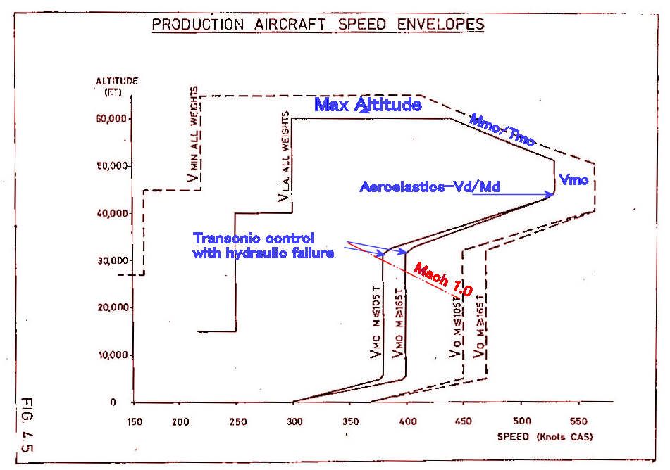
To be honest I can't remember exactly why 530 kts was chosen for the supersonic Vmo, but it was probably the best climb speed.
Mmo/Tmo was limited by a combination of intake and structural temperature.
The 'cut-off' in the sloping/530 kts boundary was, if I remember correctly, to avoid a minor aeroelastic problem at the Vd/Md condition one arrived at from that corner.
The variation of Vmo with weight was a device which, when associated with the CG corridor, allowed the aircraft to meet the manoeuvre requirements when flying on half hydraulics.
400 kts CAS gave 0.93M at around 28000 ft if I recall correctly, which was just below drag rise and gave optimum subsonic cruise performance
Last edited by Jetdriver; 21st April 2012 at 00:33 .
Subjects
C of G
Intakes
Vmo
Links are to this post in the relevant subject page so that this post can be seen in context.
Reply to this quoting this original post. You need to be logged in. Not available on closed threads.
April 21, 2012, 00:45:00 GMT
permalink Post: 7147140
Which also contain other Boxes such as the Radio Tran-ceivers, ADF receivers and Intake Computers among them which are all coverd over and out of site!
They did survive the Paris Crash from memmory.
Subjects
Air France 4590
Intakes
Links are to this post in the relevant subject page so that this post can be seen in context.
Reply to this quoting this original post. You need to be logged in. Not available on closed threads.
April 27, 2012, 20:29:00 GMT
permalink Post: 7159636
2) AFAIK pretty standard:
Q from pitots
S from statics
T from temp probe
Modified by ADC for position error. It's possible that ADC used beta inputs and I'm sure it used alpha inputs to achieve this.
1) So there is a direct temp reading, from the TAT probe. But where is TAT probe? Is it in the needle nose probe that also measures pitot/static for the intake computers? And how many TAT sensors are there (failure of a single one if that's all there is would not be good)?
2) Mach comes from dynamic pressure (pitots), from static ports, and from temp. But what temp? OAT perhaps?
Subjects
ADC (Air Data Computer)
Intakes
Skin Temperature
Stagnation Point
Static Ports
TAT (Total Air Temperature)
Links are to this post in the relevant subject page so that this post can be seen in context.
Reply to this quoting this original post. You need to be logged in. Not available on closed threads.
June 25, 2012, 15:13:00 GMT
permalink Post: 7261526
It would take a book to answer your questions properly. Luckily someone has already written it - try to get hold of Ken Owen's "Concorde New Shape in the Sky" ISBN 0 7106 0268 5. It is an excellent account of the genesis and development of the machine that drove my life for 25 years.
You are right - it was a political agreement, but politics after all the art of agreeing what is possible, and we are talking of the UK and France of the 1950s. No way that either of those two proud countries was going to let the other have the lion's share of the kudos and fun of developing and flying the world's first supersonic airliner. Fun? yes, exciting, challenging, exhausting but definitely fun.
and no way it was going to be other than an equal split.
But one can easily argue that it was arranged so that each country contributed the best it had to offer. The actual split was 50/50 on total costs, but arranged so that the UK had 60% of powerplant and 40% airframe. At the time, France had nothing to compare with the Olympus as an engine suitable for supersonic cruise, so that was logical. Out of our 40% on airframe we had responsibility for the intake and for powerplant/airframe integration. But when it came down to brass tacks Onera had a more flexible intake design than anything we Brits had to offer, and later in the project the "TRA" nozzle also came from France. We can take a lot of credit for melding these into a very successful powerplant, but I think it fair to say that each country did, in fact, contribute the best it had to offer.
As for fair shares for all, well all I can say is that there was more than enough work to go around

Subjects
Intakes
Nozzles
Links are to this post in the relevant subject page so that this post can be seen in context.
Reply to this quoting this original post. You need to be logged in. Not available on closed threads.