July 09, 2012, 19:30:00 GMT
permalink Post: 7286483
Subjects
Intakes
Olympus 593
Super-cruise
Links are to this post in the relevant subject page so that this post can be seen in context.
Reply to this quoting this original post. You need to be logged in. Not available on closed threads.
August 01, 2012, 18:47:00 GMT
permalink Post: 7337715
Subjects
Intakes
Links are to this post in the relevant subject page so that this post can be seen in context.
Reply to this quoting this original post. You need to be logged in. Not available on closed threads.
August 04, 2012, 11:43:00 GMT
permalink Post: 7341902
I don't think there is any published explanation, but maybe this will help.
Basically the problem with #4 intake was that it was on the RHS of the airplane. We are talking about low speed right? and especially zero forward speed when the engine is trying to suck as much air as it can get from wherever it can get it. That means that the induced angle of attack on all the intake leading edges is going to be high.
The best drawing I can find that shows the flow into the right hand pair is this
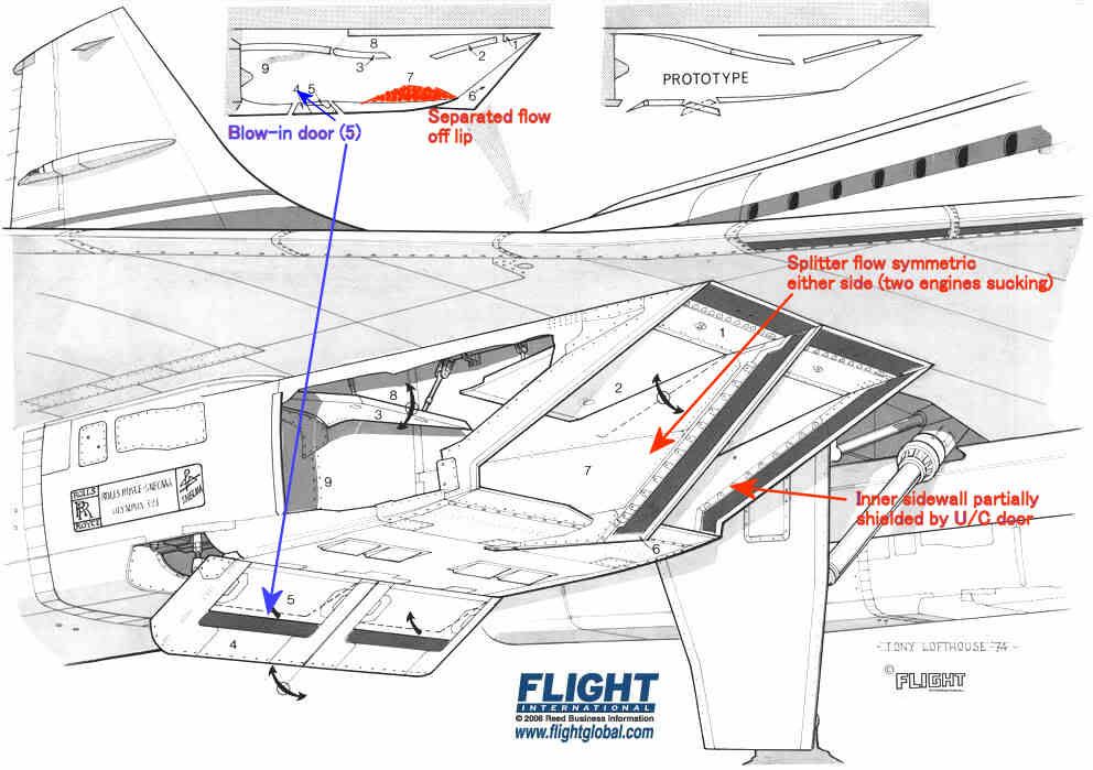
The intake leading edges were all sharp, so the flow would separate if subjected to a high AoA. The upper lip was protected a little by the wing leading edge, and we were obliged to modify the prototype LE ahead of the intakes to prevent underwing vortices developing at low AoA in cruise which also helped a bit.
The lower lip had a substantial separated flow 'bubble' at low forward speed as shown in red, but this cleared up quite quickly as the aircraft gathered speed. It was'cured' by the blow-in doors.
The inner sidewalls were shielded by the landing gear doors, so the AoAs on the sidewall on that side were quite modest.
The splitter was of course subject to equal flow demands on either side so the flow over that was pretty well symmetric.
That leaves the two outer sidewalls which, look for all the world like highly swept delta wings with sharp LEs mounted vertically.
Like all such wings when operated at high AoA they develop powerful vortices on the 'leeward' side. Looking back towards the engine the vortex on #4 engine was anticlockwise and that on #1 was clockwise. [Hope I got that one the right way round
 ]
]
The OL593 rotates clockwise looking aft so the induced incremental AoA on the compressor blades was different on #1 and #4. The difference was enough to trigger some mild blade vibration - hence the rpm restriction until the intake capture was good enough to reduce the vortex strength.
Subjects
AoA
Intakes
Landing Gear
Vortex
Links are to this post in the relevant subject page so that this post can be seen in context.
Reply to this quoting this original post. You need to be logged in. Not available on closed threads.
September 01, 2012, 00:31:00 GMT
permalink Post: 7389575
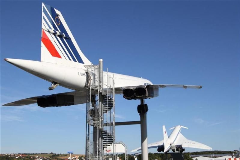
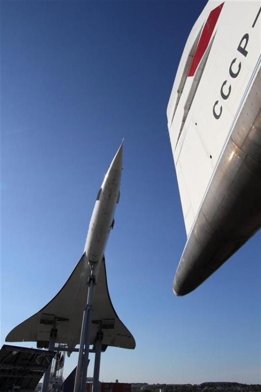
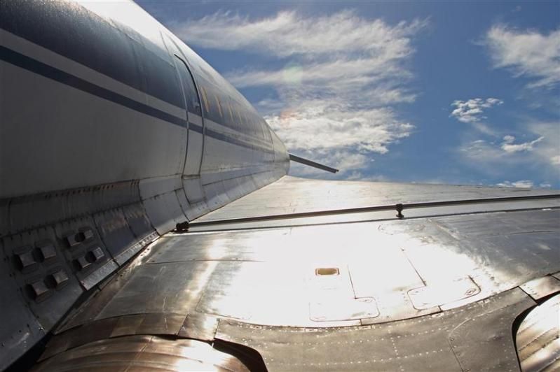
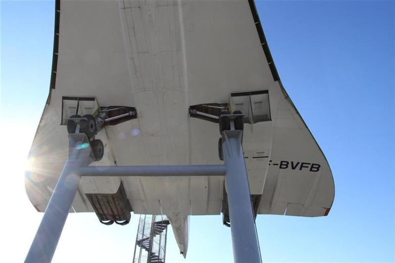
Anyway, of relevance to this thread I thought I'd shared some of my photos of Concorde F-BVFB and Tupolev TU-144 77112. It was tremendous to be able to walk backwards and forwards between the two, directly comparing design features and relative elegance of execution. Both are achievements for mankind but I have to say that to me not being an aeronautical engineer, Concorde won every time - dreary Air France cabin notwithstanding - with the larger Tupolev coming over as somewhat clumsy; let alone knowing engine technologies to be a world apart, just compare the wheel bogies as one example, and then the cleanliness of wing design as another. Yes, the Tupolev canards were a novel feature, but I understand they were only necessary in the first place because of lower speed control issues as a result of more basic aerodynamics.
Like any aircraft on static display exposed to the elements both airframes could do with some TLC, but here are the photos:
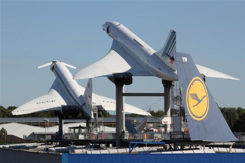
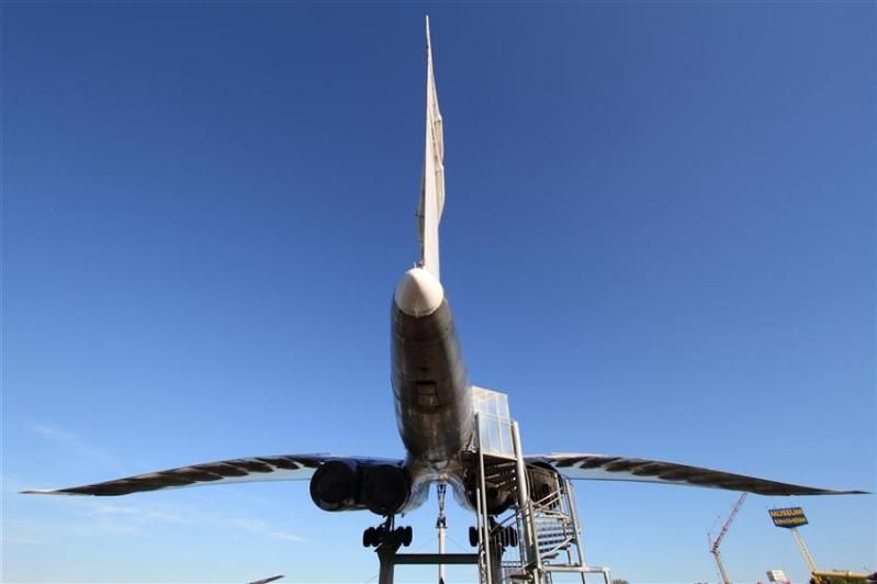
Concorde aft cabin door
TU-144 aft cabin door
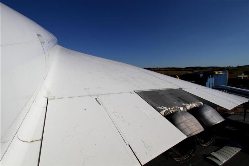
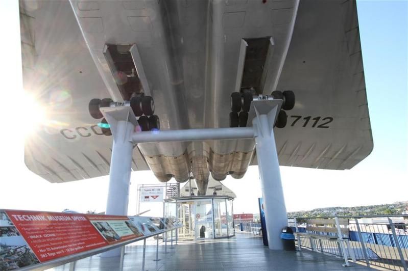
TU-144 No 4 engine location viewed from exhaust towards inlet (and directly in to the sun!)
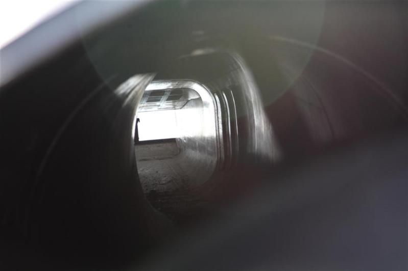
To be continued in separate post as I have hit the photo count ceiling in this one.
Subjects
Intakes
Tu-144
Links are to this post in the relevant subject page so that this post can be seen in context.
Reply to this quoting this original post. You need to be logged in. Not available on closed threads.
October 27, 2012, 02:22:00 GMT
permalink Post: 7488719
Whilst looking for some engineering background on the intake flow I came across this paper which goes into some detail
https://docs.google.com/viewer?a=v&q...70XxfUcy8PWNyw
The author says for example "..pressure recovery at Mach2 was 95%, with 1% of the loss attributed to subsonic diffusion,0.5% to the 1st shock,, 0.02% to the 2nd and 3.7% to the 3rd and final oblique shock."
I was looking for mention of a normal shock as I always understood that was a prerequisite for finally getting to subsonic.
A normal shock is only mentioned in connection with an alternative design with a lengthened forward ramp.
So, was there one or not? Or is it just not that simple?
Thanks.
Subjects
Intakes
Links are to this post in the relevant subject page so that this post can be seen in context.
Reply to this quoting this original post. You need to be logged in. Not available on closed threads.
October 27, 2012, 09:40:00 GMT
permalink Post: 7488997
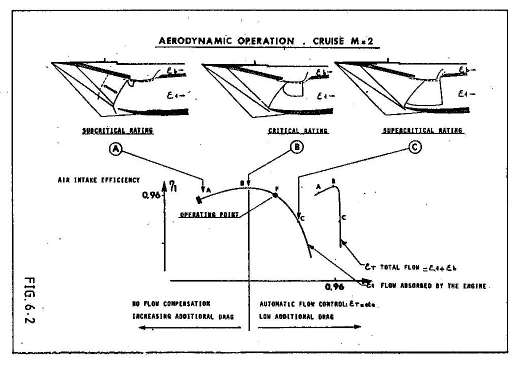
In normal operation (centre picture), the flow in the upper half of the intake was supersonic with a normal shock as required to decelerate to subsonic conditions. In the lower half the flow was decelerated to just sonic by the cowl shock. If the engine demand increased the region of supersonic flow got bigger until it nearly filled the intake (right hand picture).
The small reversed "D" zone just below the bleed slot is the supersonic region. The bleed flow entered the bleed aft of the normal shock.
Last edited by CliveL; 27th October 2012 at 09:44 .
Subjects
Bleed Air
Intakes
Links are to this post in the relevant subject page so that this post can be seen in context.
Reply to this quoting this original post. You need to be logged in. Not available on closed threads.
October 28, 2012, 08:16:00 GMT
permalink Post: 7490288
As you say, a complex subject!
Maybe the missing link is that a plane shock is not the only way to decelerate through Mach 1.0. If the nose of a body is blunt, or if the angle you are trying to turn the flow through is too big then the shock wave becomes detached from the leading edge of the body. The bit of the shock on the 'cusp' is then actually a very strong plane (normal) shock and the flow immediately behind that part is subsonic. In the case of a sharp surface with a large tuning angle this subsonic flow allows air to escape from the high pressure side of the surface to the low pressure side. This would be the case for example if the flow onto the leading edge of an intake hit it at too big an angle.
Supersonic intakes come in two basic guises - external compression and internal compression. The ramjet intakes you have been reading about are the latter type in which all the deceleration/compression takes place inside the intake. In these designs the final compression is through a normal shock situated at the minimum area 'throat' of the intake where the flow is close to Mach 1.0. This flow is delicately balanced and if some engine disturbance causes the shock to move into the converging supersonic bit of the intake the whole shock system can be expelled giving all sorts of problems (inlet unstart). Generally they are used for high Mach numbers where their higher theoretical efficiency and low external/spillage drag count for more than the additional control system complexity and performance requirements.
In external compression intakes (a simple pitot intake would be an extreme example), all the compression is done by a system of shock waves that sit outside the intake. These intakes are less efficient than internal compression intakes and they also spill a lot of air which produces external drag. Usually restricted to low supersonic Mach numbers.
Concorde's intake was a "mixed compression" design which had some features of each type. At low engine mass flow demands the flow coming on to the cowl lip could be at too great an angle to maintain attached shock waves so it behaved a bit like that described earlier. You can see this most clearly in the left hand picture where the lower efficiency and higher spillage can be seen in the graph of efficiency against intake capture (epsilon). In this state the intake behaved more like an external compression type and there was no appreciable final normal shock.
At high engine demand the angle of flow hitting the cowl was such that the shock waves remained attached and the intake functioned more like an internal compression design. Again you can see this in the right hand picture which shows most of the intake throat covered by a normal shock and in the graph where total intake flow (engine plus bleed) is constant.
On condition there was a bit of each, but since it was designed to minimise spillage you cannot see the detachment of the cowl lip shock at the scale of the diagram.
Hope this is helpful rather than additionally confusing!
PS: Looking at the centre picture again, it occurs to me that the curved shock running from the lip back and up to the reversed "D" would actually be normal to the approaching local flow which was being turned by the ramps and the isentropic compression. This would be the shock you are looking for to decelerate the flow to subsonic conditions. In other words the intake was functioning as an external compression design over this part.
Last edited by CliveL; 28th October 2012 at 08:28 .
Subjects
Bleed Air
Intakes
Links are to this post in the relevant subject page so that this post can be seen in context.
Reply to this quoting this original post. You need to be logged in. Not available on closed threads.
February 23, 2013, 09:06:00 GMT
permalink Post: 7710332

Once it was decided to go, I would say that the system requirements were largely driven by the difficulty of the task - more a question of finding out how to make it work than of optimising. The overall aircraft requirements were driven by the engineers, but criticised by the potential customer airlines in regular meetings.
Safety requirements were specified in a completely new airworthiness code - a sort of comprehensive set of special conditions, which were generally more severe than the subsonic codes of the time. Concorde, for example, was, AFAIK , the first civil aircraft to be certificated against the requirements that now exist as 25.1309.
But nobody really knew what to write for supersonic flight and, in particular, the transition from subsonic, so to some extent one made it up as one went along, using prudent common sense and engineering judgement. Fuel system transfer rates for example had to match a requirement that it should be possible to abandon the acceleration at any point and return safely to subsonic conditions - and the deceleration was much quicker than the acceleration!
 Supersonic testing mainly at 1/30 scale; low speed 1/18. The biggest model was a 1/6 scale half model used mainly for icing tests. Isolated intake tests, IIRC, about 1/10 scale, but we did have a full scale intake operating in front of an Olympus 593 at Mach 2.0 in Cell 4 at NGTE Pyestock.
Subjects
Intakes
Olympus 593
Links are to this post in the relevant subject page so that this post can be seen in context.
Reply to this quoting this original post. You need to be logged in. Not available on closed threads.
May 08, 2013, 16:05:00 GMT
permalink Post: 7832495
Accueil
This site has a database of thousand of concorde flights with the following datas: Date and time of the flight, airframe used, technical and commercial crews, guests, departure/arrival airports and flight type (regular, charter world tour...).
On top of that, many infos and stories around Concorde can also be found there.
I can't resist to translate one of those stories (I'm far from being a native english speaker or a professional translator; so forgive me for the misspellings and other translation mistakes). It is a report about one of the biggest incident that happened to the prototype 001 during the flight tests:
Shock of shockwaves
We were flying with Concorde at Mach 2 since 3 month already on both side of the Channel. The prototype 001 did outstrip 002 which was supposed to be the first to reach Mach 2.
Unfortunately, a technical issue delayed 002 and Brian Trubshaw fairly let Andr\xe9 Turcat be the first to reach Mach 2 with the 001 which was ready to go.
The flight tests were progressing fast and we were discovering a part of the atmosphere that military aircrafts hardly reached before. With Concorde, we were able to stay there for hours although limited by the huge fuel consumption of the prototypes.
The Olympus engines did not reached their nominal performance yet and, most of the time, we had to turn on the reheat in supersonic cruise to maintain Mach 2.
The reheat is what we call afterburner on military aircrafts. Fuel is injected between the last compressor stage of the low pressure turbine and the first exhaust nozzle. This increases the thrust for the whole engine and its nozzle.
The 4 reheats, one for each engine, are controlled by the piano switches behind the thrust leavers on the center pedestal between the two pilots. Air was fed into the engines through 4 air intakes, one for each engine, attached 2 by 2 to the 2 engine nacelle, one under each wing. The advantage in terms of drag reduction was obvious.
However, tests in wind tunnel showed that, at supersonic speed, if a problem happens on one engine, there was a great chance for the adjacent engine to be affected as well by the shockwave interference from one air intake to the other despite the presence the dividing wall between the two intakes. So we knew that an engine failure at mach 2 would result in the loss of 2 engines on the same side, resulting in a lateral movement leading to a strong sideslip that would likely impact the 2 remaining engines and transform the aircraft into the fastest glider in the world.
This is why an automatic anti sideslip device was developed and installed on the aircrafts.
The air intakes are very sophisticated. At mach 2, it creates a system of shockwaves that slows down the air from 600 m/sec in front of the aircraft to 200 m/sec in front of the engine while maintaining a very good thermodynamic performance. In supersonic cruise, the engines, operating at full capacity all the time, were sensitive to any perturbation and reacted violently with engine surge: the engine refusing the incoming air.
Stopping suddenly a flow of almost 200kg of air per second traveling at 600m/sec causes a few problems. As a result, a spill door was installed under the air intake and automatically opened in such event.
To control the system of shockwaves and obtain an efficiency of 0,96 in compression in the air intake, 2 articulated ramps, controlled by hydraulic jacks, are installed on the top of the air intakes in front of the engines. Each ramp is roughly the size of a big dining room table, and the 2 ramps, mechanically synchronized, move up or down following the instruction of an highly sophisticated computer that adapts the ramp position according to the mach number, the engine rating and other parameters such as skidding.
At that time, it was the less known part of the aircraft, almost only designed through calculation since no simulator, no wind tunnel, did allow a full scale test of the system.
The control of the system was analog and very complex but it was not easy to tune and we were moving ahead with a lot of caution in our test at mach 2.
On the 26th of January 1971, we were doing a nearly routine flight to measure the effect of a new engine setting supposed to enhance the engine efficiency at mach 2. It was a small increase of the rotation speed of the low pressure turbine increasing the air flow and, as a result, the thrust.
The flight test crews now regularly alternate their participation and their position in the cockpit for the pilots.
Today, Gilbert Defer is on the left side, myself on the right side, Michel R\xe9tif is the flight engineer, Claude Durand is the main flight engineer and Jean Conche is the engine flight engineer. With them is an official representative of the flight test centre, Hubert Guyonnet, seated in the cockpit's jump seat, he is in charge of radio testing.
We took off from Toulouse, accelerated to supersonic speed over the Atlantic near Arcachon continuing up to the north west of Ireland.
Two reheats, the 1 and the 3, are left on because the air temperature does not allow to maintain mach 2 without them.
Everything goes fine. During the previous flight, the crew experienced some strong turbulence, quite rare in the stratosphere and warned us about this. No problem was found on the aircraft.
We are on our way back to Toulouse off the coast of Ireland. Our program includes subsonic tests and we have to decelerate.
Gilbert is piloting the aircraft. Michel and the engineers notify us that everything is normal and ready for the deceleration and the descent.
We are at FL500 at mach 2 with an IAS of 530 kt, the maximum dynamic pressure in normal use.
On Concorde, the right hand seat is the place offering the less possibility to operate the systems. But here, we get busy by helping the others to follow the program and the checklists and by manipulating the secondary commands such as the landing gear, the droop nose, the radio navigation, comms, and some essential engine settings apart from the thrust leavers such as the reheat switches.
The normal procedure consists in stopping the reheat before lowering the throttle.
Gilbert asks me to do it. After, he will slowly reduce the throttle to avoid temporary heckler. Note that he did advise us during the training on the air intake to avoid to move the thrust leaver in case of engine surge.
As a safety measure, I shut down the reheat one by one, checking that everything goes fine for each one. Thus I switch off the reheat 1 with the light shock marking the thrust reduction. Then the 3\x85
Instantly, we are thrown in a crazy situation.
Deafening noise like a canon firing 300 times a minute next to us. Terrible shake. The cockpit, that looked like a submarine with the metallic and totally opaque visor obviously in the upper position, is shaken at a frequency of 5 oscillation a second and a crazy amplitude of about 4 to 5 G. To the point that we cannot see anymore, our eyes not being able to follow the movements.
Gilbert has a test pilot reaction, we have to get out of the maximum kinetic energy zone as fast as possible and to reduce speed immediately. He then moves the throttle to idle without any useless care.
During that time, I try, we all try to answer the question: what is going on? What is the cause of this and what can we do to stop it?
Suspecting an issue with the engines, I try to read the indicators on the centre control panel through the mist of my disturbed vision and in the middle of a rain of electric indicators falling from the roof. We cannot speak to each other through the intercom.
I vaguely see that the engines 3 and 4 seem to run slower than the 2 others, especially the 4. We have to do something. Gilbert is piloting the plane and is already busy. I have a stupid reaction dictated by the idea that I have to do something to stop that, while I can only reach a few commands that may be linked to the problem.
I first try to increase the thrust on number 4 engine. No effect so I reduce frankly and definitively. I desperately look for something to do from my right hand seat with a terrible feeling of being helpless and useless.
Then everything stops as suddenly as it started. How long did it last, 30 seconds, one minute?
By looking at the flight data records afterward, we saw that it only last\x85 12 seconds!
However, I have the feeling that I had time to think about tons of things, to do a lot of reasoning, assumption and to have searched and searched and searched\x85! It looked like my brain suddenly switched to a fastest mod of thinking. But, above all, it's the feeling of failure, the fact that I was not able to do anything and that I did not understand anything that remains stuck in my mind forever.
To comfort me, I have to say that nobody among the crew did understand anything either and was able to do anything, apart from Gilbert.
The aircraft slows down and the engine 3 that seemed to have shut down restart thanks to the auto ignition system. But the 4 is off indeed.
Michel makes a check of his instruments. He also notes that the engine 4 has shut down but the 4 air intakes work normally, which makes us feel better. After discussing together, we start to think that we probably faced some stratospheric turbulence of very high intensity, our experience in this altitude range being quite limited at that time. But nobody really believes in this explanation. Finally, at subsonic speed, mach 0.9, with all instruments looking normal, we try to restart engine 4 since we still have a long way to go to fly back to Toulouse.
Michel launches the process to restart the engine. It restarts, remains at a medium rotation speed and shuts down after 20 seconds, leaving us puzzled and a bit worried despite the fact that the instrument indicators are normal.
Gilbert then decide to give up and won't try to restart this engine anymore and Claude leaves his engineer station to have a look in a device installed on the prototype to inspect the landing gear and the engines when needed: an hypo-scope, a kind of periscope going out through the floor and not through the roof.
After a few seconds, we can hear him on the intercom:
"!!!!! (stuttering) we have lost the intake number 4."
He then describes a wide opening in the air intake, the ramp seems to be missing and he can see some structural damages on the nacelle.
Gilbert reacts rapidly by further reducing the speed to limit even more the dynamic pressure.
But we don't know exactly the extent of the damage. Are the wing and the control surfaces damaged? What about engine 3?
We decide to fly back at a speed of 250 kts at a lower altitude and to divert toward Fairford where our british colleagues and the 002 are based. I inform everybody about the problem on the radio and tell them our intentions. However, I add that if no other problems occur, we will try to reach Toulouse since we still have enough fuel.
Flying off Fairford, since nothing unusual happened, we decide to go on toward Toulouse. All the possible diversion airport on the way have been informed by the flight test centre who follows us on their radar.
At low speed, knowing what happened to us and having nothing else to do but to wait for us, time passes slowly, very slowly and we don't talk much, each one of us thinking and trying to understand what happened. However, we keep watching closely after engine 3.
Personally, I remember the funny story of the poor guy who sees his house collapse when he flushes his toilets. I feel in the same situation.
Gilbert makes a precautionary landing since we don't rely much on engine 3 anymore. But everything goes fine.
At the parking, there is a lot of people waiting for us and, as soon as the engines stop, we can see a big rush toward the nacelles of the right hand side engines.
Gilbert and myself are the first to get off the plane and we are welcomed down the stairs by Andr\xe9 Turcat and Jean Franchi who came out from the crowd watching at the right hand side nacelle.
They both behave the same way, with a slow pace attitude, the same look, a mix of disbelief and frustration.
Andr\xe9 is the first to speak: "I can't believe we were not on this flight, really unlucky\x85". Yes, this flight was supposed to be just a routine flight\x85!
The condition of the nacelle is impressive. We come closer and everybody move aside for us with a look of disbelief and respect as if we were hell survivors.
The ramps of the intake 4, those 2 "dining tables", have completely disappeared leaving a hole where we can see the hydraulic jacks and the stub rod where the ramps were attached.
Indeed, only the ramps were missing, apparently ejected forward which was unbelievable knowing how fast we were flying. The ramp slipped under the nacelle causing some damages on it and on the hood of one of the elevon's servo control. Fortunately, the control did not suffer any damage.
What is left of the rear ramp seems to be blocked down inside the intake in front of the engine and we can see behind it the first blades of the compressor, or what is left of it, not much.
The engine swallowed a huge amount of metal but no vital parts of the aircraft has been damaged, no hydraulic leaks, no fuel leaks. I remembered at that time the stories of some B58 Hustler accident where the loss of an engine at mach 2 almost certainly ended with the complete loss of the aircraft. Our Concorde has only been shaken. This incident strengthened the trust I had in this plane. And I was not unhappy to have experienced this ordeal, especially when I saw the frustration on the face of Andr\xe9 Turcat and Jean Franchi.
But we had to understand what happened and how; and also why the ramp's fixing broke.
It didn't take much time to get the answers.
I unintentionally triggered the problem when shutting down the reheat of engine 3. The sudden stop of the fuel flow did of course stop the combustion and the back pressure behind the low pressure turbine. But, probably because of the modification made on the engine before the flight, the stop of the reheat has not been followed by the normal closing movement of the primary nozzle to compensate the pressure drop. So the low pressure turbine ran out of control, dragging down the low pressure compressor which reacts by surging.
Despite the opening of the spill door, the engine surge led to a sudden movement of the shockwaves in the air intake creating a surge in the intake itself. A similar surge happened in the adjacent intake 4 followed by a surge of the corresponding engine. This caused an excessive pressure above the ramps and the fixings of the intake 4 did not hold.
Since it was the first time we experienced a surge in the air intake, we had little knowledge of the stress it would create on the ramps. This led to miscalculation of the strength of the ramps's frames and they did brake.
Another mistake: instead of installing the motion detectors on the ramp itself, to make the production easier, they have been placed on the arms of the hydraulic jacks. This is why Michel R\xe9tif thought that the position of the ramps were correct. The hydraulic jacks did not suffer any damage and were still working normally even if the ramps were missing.
All the data recorded during this event helped us in redesigning the air intakes and the flight test program resumed three month later.
After this, we deliberately created dozen and dozen of air intake surge to fine tune the way to regulate them with digital calculator this time.
From now on, even if it was still very impressive, it was safe and their intensity was not comparable with what we experienced with the missing ramps.
However, a french president may kept a lasting memory of this, much later, during a flight back from Saudi Arabia. This time, I was on the left side, Gilbert on the right and Michel was still in the third seat\x85 But that's another story.
For me, the lasting impression of failing and being helpless during this incident made me wonder what a commercial pilot would have done in this situation. This plane was designed to be handled by standard commercial pilots and not only by the flight test pilots.
At that time, I was interested in taking in charge the management of a training center for the pilots of the future Airbus's clients. This event pushed me that way and I made it clear that I wanted to add the flight training on Concorde in this project. This has been agreed and I did it.
And the Concorde training program now covers the air intake surges and how to deal with them.
Jean PINET
Former test pilot
Member and former president of the Air and Space Academy
Last edited by NHerby; 9th May 2013 at 17:24 .
Subjects
Afterburner/Re-heat
Air France 4590
Andre Turcat
Brian Trubshaw
Checklists
Elevons
Engine Failure
Engine surge
Fairford
Fuel Burn
Hydraulic
IAS (Indicated Air Speed)
Intakes
Landing Gear
Nozzles
Shockwave
Sideslip
Simulator
Toulouse
Visor
Links are to this post in the relevant subject page so that this post can be seen in context.
Reply to this quoting this original post. You need to be logged in. Not available on closed threads.
October 17, 2013, 01:57:00 GMT
permalink Post: 8102737
CONCORDE - A Designer's Life by Ted Talbot
I've just found an earlier pprune post educating me on the author
QUOTE]If I may, I would now like to mention the 'some oil lamps and diesel oil' story. This is a true story told to me by Dr Ted Talbot, the father of the Concorde Intake, brilliant aerodynamicist and all round amazing gentleman.[/QUOTE]
Can't wait for it to arrive in my mail box.
Last edited by peter kent; 17th October 2013 at 02:45 . Reason: clarification
Subjects
Intakes
Links are to this post in the relevant subject page so that this post can be seen in context.
Reply to this quoting this original post. You need to be logged in. Not available on closed threads.
October 18, 2013, 21:59:00 GMT
permalink Post: 8106282
If BA (and Air France) honestly thought Concorde was a profit center (rather than brand prestige), they would have wanted more
 .
.
BTW, my comments about the flight deck were not intended as criticism - no doubt it was state of the art when it was designed. I was just commenting on how much things have changed since then.
I don't mean to dispute that the Concorde was an incredible airplane and engineering achievement. Just saying that it never really had a chance to be successful. The same thing would have applied to the Boeing SST if it hadn't been cancelled (I knew a guy that worked on the Boeing SST inlet control system - talk about complex
 ). Cancelling the SST is probably the best thing that ever happened to Boeing - it likely would have bankrupted the company.

Last edited by tdracer; 18th October 2013 at 22:01 .
Subjects
Boeing
Boeing SST
British Airways
Intakes
Links are to this post in the relevant subject page so that this post can be seen in context.
Reply to this quoting this original post. You need to be logged in. Not available on closed threads.
October 18, 2013, 22:40:00 GMT
permalink Post: 8106344
CONCORDE SST : CONCORDE B
.
). Cancelling the SST is probably the best thing that ever happened to Boeing - it likely would have bankrupted the company.
Last edited by DozyWannabe; 18th October 2013 at 23:02 .
Subjects
Boeing
Boeing 747
Boeing SST
British Airways
Brooklands
G-BBDG
Intakes
Links are to this post in the relevant subject page so that this post can be seen in context.
Reply to this quoting this original post. You need to be logged in. Not available on closed threads.
December 10, 2013, 11:44:00 GMT
permalink Post: 8198315

I would like to know how susceptible both the clever intakes and the Olympus engines were to damage from bird ingestion, and if it ever happened in flight. I assume the answer might lie in the positioning of the ramps at takeoff and bird inhabited altitudes?
Also, a theme throughout the thread has been that the two projects of the era that people wanted to work on were Apollo and Concorde. My question is; were there any companies (and particularly individuals) who were lucky enough to work in some part (large or small) on both of these marvels of engineering?
I would also be very interested to hear:
i) From the pilots - what the "worst" (both subjectively and objectively if you like) situation or failure was that you trained for in the sim or on a real aircraft.
ii) From the engineers - the "Concorde factor" aside, how was she to work on and how did her systems compare in terms of ease of maintenance to regular passenger aircraft of the day? What were the jobs/events most and least looked forward to?
iii) Any more about the de-tune facility in some of the pictures posted earlier - was its sole function to hold the bird in place and quieten the engine noise, or did it serve any other purpose (e.g. did it contain any measuring instruments).
Disclaimer: Not a pilot/engineer.
Subjects
Intakes
Links are to this post in the relevant subject page so that this post can be seen in context.
Reply to this quoting this original post. You need to be logged in. Not available on closed threads.
January 08, 2014, 07:53:00 GMT
permalink Post: 8252886
Subjects
Intakes
Links are to this post in the relevant subject page so that this post can be seen in context.
Reply to this quoting this original post. You need to be logged in. Not available on closed threads.
January 13, 2014, 11:19:00 GMT
permalink Post: 8261569
And really on-topic, was there any work done towards updating this for Concorde-B? Or did they never get that far? Or was the plan to just keep using exactly the same stuff, since it was already working so well?
Subjects
Intakes
Tu-144
Links are to this post in the relevant subject page so that this post can be seen in context.
Reply to this quoting this original post. You need to be logged in. Not available on closed threads.
January 24, 2014, 20:54:00 GMT
permalink Post: 8282252
I used to work with a design engineer who worked on the intake controls team - many an hour at work was spent listening to his stories!
But back to the thread....
In T. Talbot's book he mentions that above Mach 1.6 (?) Concorde was certified as a twin-engined aircraft due to the common intake.
As I don't know how in those days the equivalent of ETOPS was - how were the diversion airfields worked out? As today (say) ETOPS 180 is somewhat different if you're at Mach 0.83 or 2.02 :-)
Thanks!
Last edited by Hapsen; 25th January 2014 at 15:56 .
Subjects
Intakes
Links are to this post in the relevant subject page so that this post can be seen in context.
Reply to this quoting this original post. You need to be logged in. Not available on closed threads.
March 19, 2014, 21:54:00 GMT
permalink Post: 8388573
We chose the components for their environmental tests, and all the AICS components were subjected to acceptance testing when received, which was a bit of a problem sometimes because the BAC goods inwards system was so slow that some of the expensive ADC/DACs that were not quite good enough were returned to Harris, but were out of warranty by the time they were returned. The embargo was not just the 5400 TTL I/Cs but all milspec. components.
Its stretching my memory, but AICU1 was the ADC board, 2-5 were the processor, 6-10 were the prom boards. There was a bought in board (AICU 17 I think) that was supplied by ?????, that processed the sensor unit data.
The AICS was filled with redundancy, as well as the obvious 2 AICUs per intake, and 4 sensor units, the program calculated the output data with dummy inputs - twice, and if these were correct, the proper inputs were used and the result was output to the doors. On the analogue bit there were two channels for each output and at the end one output was compared with the other and if different a fail was produced.
We haven't opened the plan chests with the AICS drawings yet.
As well as the 8 AICUs on G-BOAF, we have the prototype AICU that was used on the AICS systems rig.
Subjects
ADC (Air Data Computer)
AICS (Air Intake Control System)
AICU (Air Intake Control Computer)
G-BOAF
Intakes
Links are to this post in the relevant subject page so that this post can be seen in context.
Reply to this quoting this original post. You need to be logged in. Not available on closed threads.
June 29, 2014, 16:12:00 GMT
permalink Post: 8542535
Anyone know the story on these inlets?
They were an attempt to avoid the mechanical complexities of the prototype double hinged 'barn door' combined dump door/auxiliary intake by having several 'blow-in' vanes set in the door which were locked when the door was operated as a dump door.
Had their own set of mechanical problems and the idea was abandoned in favour of a single blow-in door (production solution)
Subjects
Intakes
Links are to this post in the relevant subject page so that this post can be seen in context.
Reply to this quoting this original post. You need to be logged in. Not available on closed threads.
April 03, 2015, 19:33:00 GMT
permalink Post: 8931947
I am afraid I have only been on Concorde around a dozen times, and as I live a few miles from Duxford, you'll probably guess that's 101 now in Hangar 1. Standing in the cabin I can only imagine the experience of actually flying in her, but you guys have certainly bought her back to life in my mind at least.
While reading the thread I came up with many questions (around ten or so) and these have been answered in later exchanges on the thread, however I do have a few left over:
1. The speed freak in me always wants to know "how fast"? Notwithstanding the principles outlined on p.55 by CliveL and M2Dude, if the intake system were somehow made "more leaky" and reheat were applied, in theory at least, how much more thrust could the 4 engines produce, in "ideal" conditions (I saw somewhere that -80C had been encountered)? If you then extrapolate the drag, what sort of peak Mach number might be attainable in short bursts (ignoring for now the detrimental effect on the airframe?)
2. There was a discussion or two of the (highly theoretical, expensive and unlikely) prospect of restoring one of the airframes back to flight around p22. However I don't think I saw 101 or 102 mentioned in any of these discussions, are these even further 'gone' (101 having sat outside for 20 years)? On the other hand, would the lack of sponge-like insulation mean less corrosion might have set in?
3. Again on p.55 there is mention of (naff) paint schemes and their bad effect on skin temperature. Was the paint on Concorde specifically chosen to radiate infrared (for example) to help cooling? The SR-71 (which I also visit at Duxford regularly - how lucky am I!) of course is matt black, which presumably radiates even better? When the airframe attained thermal equilibrium at the top of the cruise, what were the relative contributions to cooling of: radiation, cold uncompressed air passing over parts of the skin, the internal aircon (cooling from the inside), etc?
4. M2Dude referred a couple of times to robbing spares from other airframes. Spares that may have been 5-8 years old? What sort of testing regime must these spare parts go through to ensure they are still fit for flight? Is it labour-intensive?
If I can opine (at the risk of having M2Dude chastise me if he still reads this - as I am not staff) the computer he mentioned on page 37 sounds to me very much like a "bit slice" computer. These were typically constructed from discrete logic and quite often had very long words - 64 or 128 bits. I only ever saw one of these in my 30-year career in computing, a rare beast indeed. And yes I remember that Mil Spec TTL - back in the day I used to pop the lid off the ceramic packages and you can look at the gates, and even watch the silicon glow if you apply a bit too much Vcc! But I digress.
Thanks again for a fascinating thread.
Last edited by a_q; 4th April 2015 at 20:12 .
Subjects
Afterburner/Re-heat
Corrosion
Intakes
Radiation Exposure
SR-71
Skin Temperature
Links are to this post in the relevant subject page so that this post can be seen in context.
Reply to this quoting this original post. You need to be logged in. Not available on closed threads.
April 05, 2015, 08:55:00 GMT
permalink Post: 8933615
There was a certification requirement for descent time from FL600 down to FL100 if I recall correctly. Can't remember the value though. In flight reverse was developed to trim some fraction of a minute off the time to get inside the requirement
@ a_q
Not sure what you mean by a "leaky" intake. At about 2.2M the first shock would hit the intake lower lip and from that point on the total intake mass flow was frozen. Increased engine mass flow could only be obtained by reducing bleed flow and that gave higher engine face flow distortions driving the engine towards surge and lower intake recovery. So engine mass flow was effectively fixed also.
Then the amount of "dry" fuel which could be added was limited because the higher Mach number increased the engine entry temperature but the maximum turbine entry temperature was fixed.
You could add thrust by using reheat, but you would not get as much as you would like because the final nozzle, being designed for 2.0M would be too small for optimum efficiency at higher Mach numbers.
Overall, IIRC we got to 2.23M in flight test. If you pushed me I would say it might be possible with reheat etc to get to 2.25 or 2.26M, but it would be a blind guess!
Subjects
Afterburner/Re-heat
Bleed Air
Engine surge
FL600
Intakes
Nozzles
Trim
Links are to this post in the relevant subject page so that this post can be seen in context.
Reply to this quoting this original post. You need to be logged in. Not available on closed threads.