January 17, 2011, 14:20:00 GMT
permalink Post: 6185022
The same logic went for the engine starting ignitors which were used Lh or Rh per sector. This logic caused more problems with starting than any other although a way was found to over come this problem
Was there LH & RH Ignition selector switch maybe?
I hope I haven't missed further comment on this since page 50 but just back off my Hols and raced through to the end.
Also on a tangent a bit; the roll out picture further on was that a Nimrod's tail in the corner of the hangar??
regards
Howie
Subjects
Ignitors
Rolls Royce
Links are to this post in the relevant subject page so that this post can be seen in context.
Reply to this quoting this original post. You need to be logged in. Not available on closed threads.
January 17, 2011, 18:40:00 GMT
permalink Post: 6185513
Yes there was an Ignitor selector labelled LH--Both--RH, however the engines would be started using only one ignitor. This caused a few small but annoying delays as if the selected ignitor failed the start would have to be stopped the starter given a cooling period and then a further engine start using the other ignitor would be attempted, however it did give a running check that both ignitors were working.
This was not very popular with the crews and the ground engineers were persuaded to test the ignitors before presenting the aircraft for service. However due to the engine starting Fuel Pump switching, this resulted with a small fire in the hangar, and so the crews were back to starting on Lh or RH ignitors.
If I remember correctly the RR Conways on the VC-10 also had 2 ignitors per engine with a LH--Both-RH selector.
If you remember, if something went wrong with the Flying control check the F/E was always busy. This gave him a chance to think up a suitable answer or even better the pilots did the check again and it now worked.
Now I have to admit coming across the hangar to consult with you boys when preparing for a new sequence of F/E "Tech Knowledge Checks". Not that we did not understand it, you understand, but mainly to make sure that we were correct before some clever line F/E informed you of your error. Very embarrising that, and I should know

Subjects
British Airways
Captains
Conversion Course
Fuel Pumps
Ignitors
Rolls Royce
Simulator
Links are to this post in the relevant subject page so that this post can be seen in context.
Reply to this quoting this original post. You need to be logged in. Not available on closed threads.
January 18, 2011, 06:28:00 GMT
permalink Post: 6186366

There was no automatic ignition selection logic as such built into the start sequence, but a manually selected L & R ignition selector switch. The reason of course to alternate L & R selection during starting was to detect otherwise dormant ignition failures if 'BOTH' was always selected. (Modern A/C with AUTOSTART do not have this problem, if an ignitor fails during the engine start sequence the other is automatically selected and an ignition status message is set on the lower EICAS screen). The ignition L/R selector switch was bypassed during engine operation by the auto-ignition system, where if the engine control unit detected a flame out (set at 58% N2) both ignitors would automatically fire up. The sequence would release onece the perceived N2 rose above 63%. The ignition system had several reliability issues, the first was the plugs themselves. Penetration into the 'can' was crucial; if it were more than about 130 thou', the tip would very quickly burn off. We soon learned that a penetration check was vital when fitting a plug and shims needed to be used to get the correct penetration. The other reliability issue was the ignition leads themselves; For the first 10 years of service they were a major pain until 'they' (Rolls-Royce) finally got it right. Also until Rolls modified the lead clipping, it could take 3 to 4 HOURS to change a lead. The dual channel HEIU itself was as good as gold, and seldom let us down, It was a very powerful 8 Joule 2KV beast, and you obviously treated it with utmost respect.
Best regards
Dude
Last edited by M2dude; 18th January 2011 at 07:28 .
Subjects
Ignitors
Rolls Royce
Links are to this post in the relevant subject page so that this post can be seen in context.
Reply to this quoting this original post. You need to be logged in. Not available on closed threads.
January 26, 2011, 21:16:00 GMT
permalink Post: 6205197
I recently read a book entitled "The Somerset & Dorset Railway, Then and Now" by Mac Hawkins. An interesting comment is made regarding Winsor Hill Tunnel (Near Shepton Mallet), which was used, in 1968, after the line was closed and lines lifted, by Rolls Royce for destructive tests on the Olympus engine destined for Concorde.
To quote the book, " Up to the late 1980's the tunnel's portals were obscured by massive steel doors, built a little in front of the stonework and supported by a frame. These where constructed as an anti-blast measure by Rolls Royce in 1968, who used the tunnel for destructive tests on the Olympus engine for Concorde. They ran an engine without oil, expecting it to blow up within 20 minutes or so, but in the event it laster for well over two hours !. The tunnel's use for this purpose was only over a few days, planning permission having been sought from Shepton Mallet RDC as a matter of course, in case an explosion caused a change in the local topography"
I originally posted the above in the Qantas A380 thread, as that seems to be all about RR trent engines & lubricating oil matters. Perhaps it's better here as a testiment to the technical savvy of RR many years ago. Anyone remember these tests ?.
Quite a good thread this. Sadly I've never flown Concorde, but have visited her at Manchester, Duxford & Yeovilton. The one at Yeovilton had the engine access door open, allowing one to gaze up into the technical wizardry of the engine. The access door itself amazed me, doubles as some sort of oil tank, complete with heavy, precision made piano type hinges !!
A model of Concorde graces the family mantelpiece.
Edited to add link regarding above story
Windsor Hill Tunnel
Lid
Last edited by flying lid; 5th February 2011 at 20:29 .
Subjects
Rolls Royce
Links are to this post in the relevant subject page so that this post can be seen in context.
Reply to this quoting this original post. You need to be logged in. Not available on closed threads.
January 30, 2011, 14:25:00 GMT
permalink Post: 6212624
Also I heard of a similar test on the RB199; ran it up on a test bed to full power and let it stabilise for a few minutes, drain the Lube Oil Tank and stand back to see what happens - 24 hours later they gave up as it was still running !!
Possibly a standard RR development test ?

regards
Howie
Subjects
G-BOAC
Rolls Royce
Links are to this post in the relevant subject page so that this post can be seen in context.
Reply to this quoting this original post. You need to be logged in. Not available on closed threads.
April 03, 2011, 21:16:00 GMT
permalink Post: 6348525
The F/O calls Positive Climb and you call for the Gear Up . On passing 20 feet radio height, and having checked the aircraft attitude, airspeed and rate of climb are all satisfactory, the F/O calls Turn and you slowly and smoothly roll on 25\xb0 left bank to commence the turn out over Jamaica bay. Some knowledgeable passengers will have requested window seats on the left side of the aircraft at check-in, and are now being rewarded with a very close look at the waters of Jamaica Bay going by very fast! As you accelerate through 240 kts, the F/O calls 240 and you pitch up to 19\xb0 to maintain 250 kts and keep the left turn going to pass East of CRI.

Subjects
Afterburner/Re-heat
Fuel Burn
Rolls Royce
Rudder
V1
V2
Links are to this post in the relevant subject page so that this post can be seen in context.
Reply to this quoting this original post. You need to be logged in. Not available on closed threads.
April 08, 2011, 07:13:00 GMT
permalink Post: 6357473
One of the real beauties of the Concorde intake was that it was completely self-startiing, and so unstarts as such were never heard of.
Regarding the vibrations thing, here is my post #80:
Subjects
Intakes
LP Compressor
N1 (revolutions)
Rolls Royce
Vortex
Links are to this post in the relevant subject page so that this post can be seen in context.
Reply to this quoting this original post. You need to be logged in. Not available on closed threads.
April 09, 2011, 01:35:00 GMT
permalink Post: 6359223
Subjects
Intakes
Rolls Royce
Links are to this post in the relevant subject page so that this post can be seen in context.
Reply to this quoting this original post. You need to be logged in. Not available on closed threads.
August 16, 2011, 09:50:00 GMT
permalink Post: 6643157
Today\x92s world sees flying as cheap and very unglamorous.
Which ones sell better and make more profit for their manufacturers ?
Which British cars are still built ? The Morris or the Mini? Or maybe the Jaguar, Rolls Royce, Range Rover or Aston Martin ?
Of course there is no market for 1000 new Concordes, but maybe for 100. There are still enough people around that pay any price if only they can be special. There are still enough people for whom time is BIG money, and arriving before you depart easily pays off for those. Working the morning in London and having lunch with business partners in New York and signing the contracts in the afternoon is still very attractive.
Subjects
Rolls Royce
Links are to this post in the relevant subject page so that this post can be seen in context.
Reply to this quoting this original post. You need to be logged in. Not available on closed threads.
November 17, 2011, 00:00:00 GMT
permalink Post: 6811291
On Wikipedia they tell us there were 20 Concordes built, 14 production and 6 pre production
There were two prototypes , 001 and 002 (the ones with the odd porthole visors).
There were two preproduction aircraft: 01, the British one, with a full 'look-through' visor' and 02, the French one, the first one that looked like the production model, with both a 'full' visor, and the 'pointy' tail.
Then there were two 'near-production' aircraft, that were used for certification, route-proving, and suchlike, but that never entered airline service (201 and 202, now best known as 'F-WTSB' and "Delta-Golf").
And yes, then there were 14 production aircraft, that in the end all made it into service with BA and AF.
Forgive me but this does not seem possible, not enough engines were built to satisfy 'new' engines for 'new' planes on the production line.
The '67' figure probably refers only to the version of the 593 engnes for the production aircraft (4x14=56, plus spares), and not to the earlier versions used for development/testing, for the prototypes, the preprods and the cerification aircraft.
Funnily enough, there's a current discussion on a French Concorde forum on the same subject, trying to figure out not only exactly how many engines were built, but also the "where are they now?".
It would be a nice item to add to the "Concorde Story". We may have to appeal to the RR Historical Trust to open their archives, and tell us exactly how many Olympus 593's were built, and what they can tell us about their history.
CJ
Subjects
Air France
British Airways
F-WTSB
Olympus 593
Rolls Royce
Visor
Links are to this post in the relevant subject page so that this post can be seen in context.
Reply to this quoting this original post. You need to be logged in. Not available on closed threads.
December 06, 2011, 12:39:00 GMT
permalink Post: 6845507
Concorde Rolls-Royce Olympus 593-610 Turbojet Engine with Reheat | eBay
Subjects
Afterburner/Re-heat
Rolls Royce
Links are to this post in the relevant subject page so that this post can be seen in context.
Reply to this quoting this original post. You need to be logged in. Not available on closed threads.
July 24, 2012, 15:11:00 GMT
permalink Post: 7312412
Congratulations to all for a fascinating read
Although I never got the opportunity to fly on Concorde, I will never forget seeing her fly some charters from Filton in the late 1990's. On one occasion I was stood at the wire fence at the end of runway 27 and watched Concorde taxi directly towards me, do a 360 degree turn and line up for takeoff. Concorde was only around 100ft-150ft away from me when the throttles were opened. Luckily I was holding tightly onto the fence and got a face full of dust as the reheats kicked in!
 The noise, power and heat I felt from those Olympus engines was phenomenal. She looked stunning as she rotated amongst the heat haze and the slender delta climbed steeply away towards the Bristol Channel. What an aircraft!
My grandfather worked on the Olympus 593 engines at Rolls Royce in Filton, so I will always hold Concorde close to my heart. I have been onboard Foxy at Filton when she was open to the public and I have visited 002 at Yeovilton and 101 at Duxford. I live quite close to Delta Golf at Brooklands and have been onboard her about 4 times now (including a sit in the cockpit) and recently flew the fantastic Concorde simulator with Captain John Eames and First Officer Ian Smith which is a day I will treasure. Opening up the throttles for take-off on 31L at JFK and tackling the checkerboard landing at Kai Tak were experiences I will never forget.
Keep up the great postings everyone!
Subjects
Afterburner/Re-heat
Brooklands
Captains
Concorde Simulator
Filton
G-BBDG
JFK
Olympus 593
Rolls Royce
Simulator
Links are to this post in the relevant subject page so that this post can be seen in context.
Reply to this quoting this original post. You need to be logged in. Not available on closed threads.
October 31, 2012, 22:58:00 GMT
permalink Post: 7496372
rod
"Development of Pollution Controls for Rolls-Royce RB211 and Olympus 593 Engines" by A B Wassall. I have picked out stuff relevant to the question:
The engines of the day generated smoke in the primary zone and partially consumed it in the rest of the combustor.
It was easier to reduce the production than increase the consumption but leaning the primary zone had an adverse effect on relight capability which then needed its own corrective action as was done on the 211. Metal temperatures went up with the leaning (as intimated by Joliste)
The 593 did not have the leaning option as it had to maintain an over-rich primary zone at TO to ensure an adequate weak extinction margin when throttled back at completion of supersonic cruise when the combustor had to operate at A/F ratios over 180.
In addition to the smoke problem the combustor weight and pressure loss had to be reduced.
These other two requirements led to the annular combustor and vaporizers which also reduced the smoke substantially. These three benefits were expected based on Pegasus experience.
Subjects
Air France
Olympus 593
Relight
Rolls Royce
Links are to this post in the relevant subject page so that this post can be seen in context.
Reply to this quoting this original post. You need to be logged in. Not available on closed threads.
October 10, 2013, 01:12:00 GMT
permalink Post: 8090941
The ORIGINAL design for the reheat was done by SNECMA, but due to them getting into all sorts of trouble with the fuel injection system and flame stabilisation, Rolls-Royce baled them out, and it became a Rolls-Royce/ SNECMA design.
ref heritageconcorde.com
Does anyone have any details on the 'joint' development alluded to above?
Thanks.
Last edited by peter kent; 10th October 2013 at 01:14 .
Subjects
Afterburner/Re-heat
Rolls Royce
Links are to this post in the relevant subject page so that this post can be seen in context.
Reply to this quoting this original post. You need to be logged in. Not available on closed threads.
October 14, 2013, 15:06:00 GMT
permalink Post: 8098479
ref heritageconcorde.com
Does anyone have any details on the 'joint' development alluded to above?
The problem apparently was that flame stabilisation operating in "contingency" rating was sensitive to the point that every engine had to be checked, so there was a lot of engine plus reheat testing, most of which was done at Patchway. The solution was addition of some form of 'spike' at various points on the spray bar (my informant wasn't very specific). It sounded like a sort of vortex generator cum chine that gave the flame somewhere to latch onto. The development process was, as you suggested, a joint activity.
Subjects
Afterburner/Re-heat
Rolls Royce
Vortex
Links are to this post in the relevant subject page so that this post can be seen in context.
Reply to this quoting this original post. You need to be logged in. Not available on closed threads.
October 14, 2013, 23:34:00 GMT
permalink Post: 8099204
 ), the reheat was certain to set off a random sprinkling of car alarms on the airfield, which used to make my day when lucky enough to be returning to the car park around midday at LHR.
Even without reheat, however, the engine had a distinctly military sound - quite unlike other civil turbojets I can remember. The sound of it in the descent at about 4000ft over my house at 5 pm daily was unmistakeable. On the approach, if you weren't expecting it, it could be quite unnerving. One night in the late 1970s, during a long car journey, I stopped for a call of nature at a well-known public house near Hatton Cross (about a mile from touchdown on LHR 27L). It was pitch dark, and I decided that the hedge at the side of the car park would be a suitable venue. Never having heard Concorde on the approach before, I became increasingly nervous as the sound, initially unidentified, got progressively louder. And then the landing lights were switched on...
Subjects
Afterburner/Re-heat
Bristol Siddeley
LHR
Landing & Taxy Lights
Rolls Royce
Links are to this post in the relevant subject page so that this post can be seen in context.
Reply to this quoting this original post. You need to be logged in. Not available on closed threads.
July 29, 2016, 18:40:00 GMT
permalink Post: 9455879
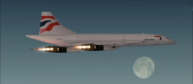
Just found this pic on the www and I think the reheat looks a bit ragged compared to the Reheated Engines I have worked on - RR Spey & RB199.
Is this a representative sort of view or a false picture and the real thing is much neater with Mach Diamonds and the like???

Subjects
Afterburner/Re-heat
Rolls Royce
Links are to this post in the relevant subject page so that this post can be seen in context.
Reply to this quoting this original post. You need to be logged in. Not available on closed threads.
November 01, 2023, 22:33:00 GMT
permalink Post: 11531535
I am trying to identify the function of two printed circuit boards from an Olympus 593 Engine Engine Control Unit (ECU). I worked on Concorde and its ECUs at Filton for many years in the 1970s and 80s.
When Concorde retired in 2003 I requested from British Airways and was given 2 ECU PCBs as a souvenir.
There were of course 8 ECUs on each aircraft, 2 per engine. Each ECU had about 20 different PCBs. I have sometimes wondered just what the function was of my 2 PCBs. Maybe someone knows or has the relevant ECU Overhaul Manual. I have already asked various organisations for help - Ultra Electronics the manufacturers of the ECUs, British Airways, Rolls-Royce Heritage Trust and some museums. I've had some helpful replies but no actual answers.
Marked on the PCBs ae their drawing numbers: 46546-629-0 and 46456-602-0.
I have tried to attach some photos but there seems to be some forum setting that's preventing this!
Thanks
Subjects
Filton
Olympus 593
Rolls Royce
Links are to this post in the relevant subject page so that this post can be seen in context.
Reply to this quoting this original post. You need to be logged in. Not available on closed threads.
November 10, 2023, 08:35:00 GMT
permalink Post: 11536526
I am trying to identify the function of two printed circuit boards from an Olympus 593 Engine Engine Control Unit (ECU). I worked on Concorde and its ECUs at Filton for many years in the 1970s and 80s.
When Concorde retired in 2003 I requested from British Airways and was given 2 ECU PCBs as a souvenir.
There were of course 8 ECUs on each aircraft, 2 per engine. Each ECU had about 20 different PCBs. I have sometimes wondered just what the function was of my 2 PCBs. Maybe someone knows or has the relevant ECU Overhaul Manual. I have already asked various organisations for help - Ultra Electronics the manufacturers of the ECUs, British Airways, Rolls-Royce Heritage Trust and some museums. I've had some helpful replies but no actual answers.
Marked on the PCBs ae their drawing numbers: 46546-629-0 and 46456-602-0.
I have tried to attach some photos but there seems to be some forum setting that's preventing this!
Thanks
Subjects
Filton
Olympus 593
Rolls Royce
Links are to this post in the relevant subject page so that this post can be seen in context.
Reply to this quoting this original post. You need to be logged in. Not available on closed threads.
November 26, 2023, 13:26:00 GMT
permalink Post: 11546242
Whether either of them would release it to you, even now, I am doubtful.
Subjects
Airbus
Rolls Royce
Links are to this post in the relevant subject page so that this post can be seen in context.
Reply to this quoting this original post. You need to be logged in. Not available on closed threads.