December 21, 2010, 12:09:00 GMT
permalink Post: 6135352
Sorry EXWOK, but I just don't agree that the aircraft was statically unstable in pitch at approach. When I think of the hours we put in trying to straighten that damned pitch curve!
It WAS designed to operate with low CG margins on approach, and that meant that the elevator (elevon) deflection needed to trim any desired incremental 'g' was quite small. On the other hand the pitch inertia was high and the elevon moment arm low, so if you just applied the elevon needed for the final state the pitch response would have been pathetic. This meant that the elevon needed to be 'overdriven' to get the aircraft moving and then backed off to hold it to the desired final state. Maybe the apparent reversals you are seeing in the video come from this source.
CliveL
Subjects
Auto-stabilisation
C of G
Elevons
Trim
Links are to this post in the relevant subject page so that this post can be seen in context.
Reply to this quoting this original post. You need to be logged in. Not available on closed threads.
December 21, 2010, 20:20:00 GMT
permalink Post: 6136200
The Mach trim control law
The aircraft response to a double engine surge
Split into two halves (longitudinal and lateral response)
Note the almost immediate rudder response, long before the engine N2 rpm starts to wind down. I'll have something to say about that in a separate post....
CJ
Subjects
Engine surge
Mach Trim
Rudder
Trim
Links are to this post in the relevant subject page so that this post can be seen in context.
Reply to this quoting this original post. You need to be logged in. Not available on closed threads.
December 22, 2010, 20:13:00 GMT
permalink Post: 6138211
Ultimately applied a further nose down elevon input (4 degrees????) if EAS was less than (140kts???? That's a VERY low speed). (Colloquially known as 'super-duper stab' on my course)
To cover this case the 'superautostabiliser'was developed. It effectively restricts the rate of variation of incidence so that, if the pilot entered into an avoidance manoeuvre of sufficient magnitude to trigger the stick wobbler, i.e. about 1.5g, he would be able to recover easily without exceeding the maximum incidence demonstrated in flight (which was in fact slightly greater than the maximum steady incidence limit). This superautostab had gain scheduled against AoA and also included phase advanced pitch rate and speed terms. Finally, there was a 'yaw superautostabiliser which applied rudder as a function of lateral acceleration to restrict sideslip which (see below) could affect the maximum lift attainable. [Note that because of the dynamics of slender aircraft operating at high AoA it was readily possible to develop sideslip in a turn]
Hope that is clear.
Whilst talking about maximum lift etc. can I confirm the numbers quoted in an earlier posting for the start of vortex lift - about 6 or 7 deg AoA at low speed, and for the AoA at maximum lift - about 23 deg. This is where the pitching momemt curve vs AoA 'breaks'. It is not a stall in the conventional sense because of course the flow over the leading edge has been separated long ago. Instead it is the AoA at which the LE vortices become 'too big for their boots' and go unstable and 'burst'. This AoA is sensitive to sideslip and the leading wing half will go first.
CliveL
Subjects
AFCS (Automtic Flight Control System)
AoA
Auto-trim
Elevons
Mach Trim
Rudder
Sideslip
Trim
Vortex
Links are to this post in the relevant subject page so that this post can be seen in context.
Reply to this quoting this original post. You need to be logged in. Not available on closed threads.
December 22, 2010, 20:40:00 GMT
permalink Post: 6138255
Closed loop
As an example, let's look (very simplified) at how the autopilot maintains a selected altitude.
On the one hand we have the desired altitude as selected on the autopilot controller (here 40,000 ft).
On the other hand we have the true altitude , as measured by the altimeter (let's say 39,000 ft).
We subtract the two to obtain the altitude error (in this case 39,000-40,000=-1,000 ft).
We 'multiply' the altitude error by a factor, the gain (for the discussion, let's assume this gain is 1 degree elevon per 1000 ft altitude error), and send the resulting elevon position command to the elevon.
So, the elevon moves 1\xb0 nose-up, the aircraft starts to climb, the altitude increases and the altitude error decreases until it becomes zero, by which time the elevon position has also returned to zero.
What we have now is a "closed loop" : any deviation from the selected altitude results in an elevon command in the opposite direction, until the deviation is again reduced to zero.
Another commonly used term is "feedback" : any error is fed back in the opposite sense until it's reduced to zero.
The significant figure here is the 'gain'.
If the gain is too small, the autopilot response to a disturbance (say turbulence) will be sluggish ; the aircraft takes too long to return to the desired altitude.
If the gain is too high, a small disturbance will cause the aircraft to start climbing too rapidly, and to overshoot the desired altitude, then descend to correct the new error, etc.
In other terms, the control loop is no longer stable, but starts to oscillate.
Both theory and practice show that the exact value of the gain is not all that critical, a few percent more or less do not markedly change the response of the loop.
Note: a "closed control loop" as described above can be implemented in just about any way you like.
It can be done purely mechanically, with a few clever clockwork mechanisms 'computing' the altitude error and controlling the elevator pneumatically or hydraulically. It's how the earliest autopilots worked.
After that came electromechanical systems, analogue computers and then digital computers... but the principle has remained unchanged.
Open loop
As already described in earlier posts, the situation with the automatic trim is the opposite.
We now need to compute a neutral elevon position from several data, such as Mach number or airspeed, but without any feedback as to whether our computations are correct.
We're now working in "open loop".
To complicate matters... that neutral elevon position is not a simple linear function of Mach and airspeed, but far more complex (see the earlier posted graphs).
And because of the large response of the aircraft to small changes in trim, in particular in the transonic regions, those computations have to be far more accurate : a one degree error is simply not acceptable.
In the end.....
The AICS (air intake control system) also uses several "open loop" functions.
The early development aircraft still had an analogue system, which proved all too soon to be inadequate, so, at a very late stage, it was replaced by a digital system (one of the rare digital systems on Concorde).
The "open loop" functions of the autotrim system initially had the typical "a few" percent" accuracy of the other flight control systems, which, for the autotrim, also proved inadequate.
We managed to "save the furniture" (as they say in French) by using 0.1% components in all the critical computing paths, so the autotrim computers remained analogue until the end.
But, a slide rule is not accurate to 0.1%... So that's when I had to buy my very first pocket calculator.
\xa342 at 1972 prices... just as well the firm paid.
CJ
Subjects
AICS (Air Intake Control System)
Auto-pilot
Auto-trim
Elevons
Intakes
Trim
Links are to this post in the relevant subject page so that this post can be seen in context.
Reply to this quoting this original post. You need to be logged in. Not available on closed threads.
December 23, 2010, 00:39:00 GMT
permalink Post: 6138601
Digging out the old BAe conversion course notes:
The "Anti-Stall" (SFC) 1&2 sytems offered:
Super Stab: Increased authority of pitch autostab as incidence increased above 13.5 degrees - proportional to pitch rate and incidence angle - and a nose down pitch trim with a Vc (CAS) deceleration with incidence > 13.5
Stick "Wobbler": the "unmistakable warning" - when incidence > 19 and Vc<270kts the control columns took a life of their own and tried to fling you into the forward galley. Served you right.
Some other high incidence stuff was fed from the ADC rather than the SFC, like:
The ">13.5d incidence" feed to the SFC
CAS (Vc) feed to the SFC
Incidence from 16 to 19 degrees (rate dependant) to get the SFC to feed in up to 4 degree nose down pitch command and the sticj wobbler trigger.
Increase of authority of yaw autostab as incidence > 13.5d
Autotrim inhibit > 14.5d incidence
Stick shaker >16.5d incidence
AP/FD disconnect > 17.5d incidence
There was loads of other technical stuff which engineers understood, but we had to learn by writing diagrams which made sense to us enough to pass the written exam. The bottom line was an aeroplane which flew beautifully, but which you had to understand well, and which you could not tease beyond its limits. If you ignored a limit or an SOP then you reached an unpleasant place far quicker than with the blunties - it was a challenge which rewarded as quickly and as deeply as it punished.
Subjects
ADC (Air Data Computer)
Auto-stabilisation
Auto-trim
Conversion Course
Fuel Burn
Galley
Stick Shaker
Trim
Links are to this post in the relevant subject page so that this post can be seen in context.
Reply to this quoting this original post. You need to be logged in. Not available on closed threads.
December 23, 2010, 03:11:00 GMT
permalink Post: 6138731
A warm welcome to the forum, please keep your most illuminating posts coming!
EXWOK
- Incidence Trim
- Super Stab
- High Incidence Directional Stability
- Auto Trim Inhibit
- Stick Shaker
- A/P disconnect
- Stick Wobbler
- IAS below 140 kts
- Incidence greater than 19\xb0
Purely in the interests of historical accuracy, may I point out that I did once complete a load sheet on a charter flight, but this occasioned such ribald comments from the starboard side of the flight deck, accompanied by ill-suppressed mirth from the maroon Mafioso in the engine room, that I decided in future to delegate all further such calculations to the F/O.

Merry Christmas to all
Bellerophon
Subjects
ADC (Air Data Computer)
Auto-stabilisation
Elevons
IAS (Indicated Air Speed)
Stick Shaker
Trim
Links are to this post in the relevant subject page so that this post can be seen in context.
Reply to this quoting this original post. You need to be logged in. Not available on closed threads.
January 14, 2011, 08:29:00 GMT
permalink Post: 6178845
The prototype had even more 'droop' in front of the intakes, but that produced a vortex at low incidence (near zero 'g') that went down the intakes and provoked surge.
Cheers
Clive
PS: Everyone seems to be adding their favourite Concorde photograph so I thought I would be different and add my LEAST favourite

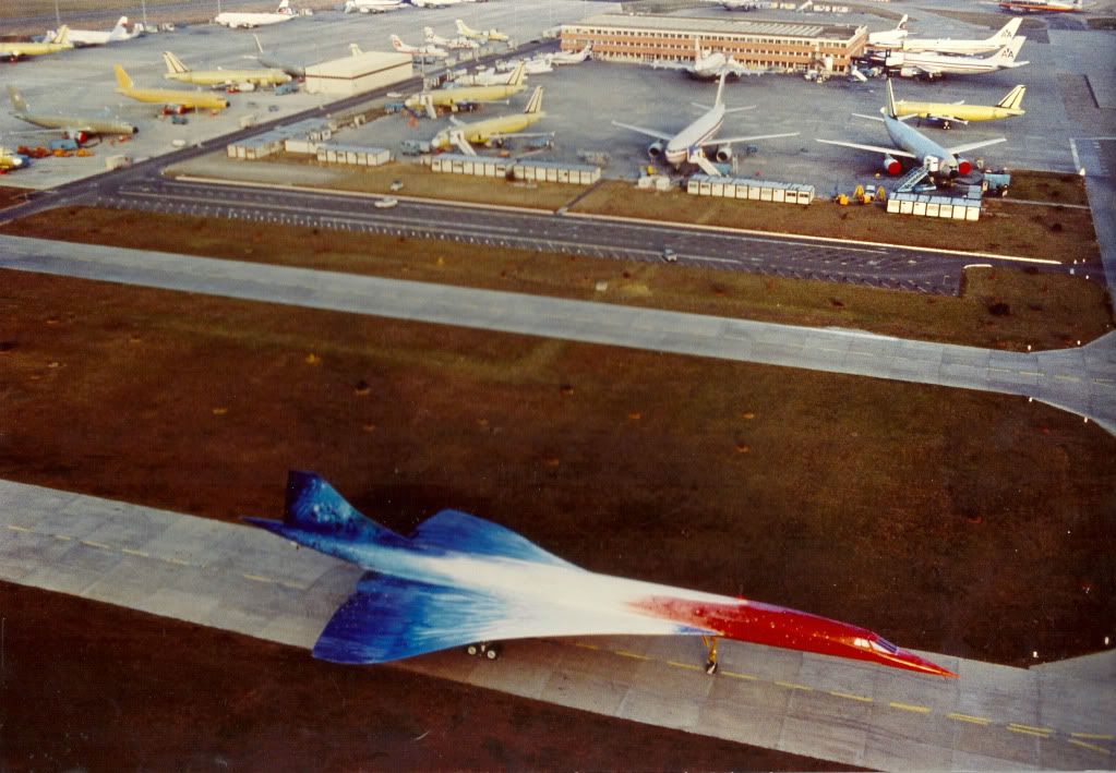 ">
">
Last edited by CliveL; 14th January 2011 at 08:43 . Reason: adding a photo and additional remarks
Subjects
C of G
Engine surge
Intakes
Trim
Vortex
Links are to this post in the relevant subject page so that this post can be seen in context.
Reply to this quoting this original post. You need to be logged in. Not available on closed threads.
April 12, 2011, 05:47:00 GMT
permalink Post: 6364687
On the planned test profile, we entered a programmed 35-deg. bank turn to the right. An immediate unstart occurred on the right engine, forcing the aircraft to roll further right and start to pitch up. I jammed the control stick as far left and forward as it would go.
No response. I instantly knew we were in for a wild ride.
The cumulative effects of system malfunctions, reduced longitudinal stability, increased angle-of-attack in the turn, supersonic speed, high altitude and other factors imposed forces on the airframe that exceeded flight control authority and the Stability Augmentation System's ability to restore control.
The next day, our flight profile was duplicated on the SR-71 flight simulator at Beale AFB, Calif. The outcome was identical. Steps were immediately taken to prevent a recurrence of our accident. Testing at a CG aft of normal limits was discontinued, and trim-drag issues were subsequently resolved via aerodynamic means. The inlet control system was continuously improved and, with subsequent development of the Digital Automatic Flight and Inlet Control System, inlet unstarts became rare.
Subjects
Air France 4590
C of G
Intakes
SR-71
Simulator
Trim
Links are to this post in the relevant subject page so that this post can be seen in context.
Reply to this quoting this original post. You need to be logged in. Not available on closed threads.
June 03, 2011, 11:35:00 GMT
permalink Post: 6490820
There were a few questions regarding ground running Concorde, so here are some 'facts' as far as I recall (Wrinkled old brain permitting).
Concorde was ALWAYS ground run in the detuners at the BA Engineering base at Heathrow, with the parking brake ON. (Save idle runs on the ramp after, say, replacing a PNC actuator etc. on departure. The required high power nozzle trim run could be deferred until the aircrafts return to LHR). Sadly I can confirm that the Concorde 'Hush House' was being demolished when I was last over the engineering patch a few weeks ago, and is probably all gone now.
The detuner chocks were like nothing else you could imagine. They were HUGE steel affairs that needed wheels to be wound down in order to move into position (took a couple of guys at least to move). Once in position forward and aft of the undercarriage, the wheels would be retracted and these 'chocks' would be tension chained together. Believe me, nothing was going to move these suckers!!

Engines WERE NOT run in symmetrical pairs, but the adjacent engine always was run at idle power. The reason for this was so that there was airflow over the T1 probe of the adjacent engine, a winding in this being used by the alternate engine control lane if needs meant it might be required if the main lane failed during the engine run. The way that the aircraft was tethered meant that symmetrical high power running was not any sort of issue.

We were very mean too. In the summer the hangar doors of TBK opposite would invariably be open during the day, the challenge was to see how long it took for us to make them close the doors to shut out the din. (Like I said, Concorde engineers were mean
 ).
).
Good to be back
Best regards to all
Dude

Last edited by M2dude; 4th June 2011 at 20:03 .
Subjects
British Airways
LHR
Nozzles
Trim
Links are to this post in the relevant subject page so that this post can be seen in context.
Reply to this quoting this original post. You need to be logged in. Not available on closed threads.
June 21, 2011, 06:14:00 GMT
permalink Post: 6526303
I have a bit more information now, although my French is very rusty so I may not have it all correct - CJ can probably correct me if necessary.
They did 8 flights over 10 hrs, preceded by about 30 simulator 'flights'. Most of the flight testing was looking at low speed behaviour, since that was where they expected to see most gains on Concorde, and where the most problems might be expected, but they did go up to 2.04M. The primary advantage was seen to be the possibility of using very aft CGs for takeoff to reduce trim drag - they flight tested as far back as 56% at around 0.4M (no consideration of limits from U/C location of course for this sort of testing). In addition they were predicting a weight saving of around half a tonne.
The simulator work sorted out the basic laws, where they tested a pure pitch rate feedback and a C* law with load factor and pitch rate terms. The pilots preferred the latter (which became in time the basis for the A320 laws).
The simulator was also used to establish the best ergonomics (movement and force harmonisation) of the sidestick.
The 'blue' electrical signalling system for elevons was replaced by the digital control and sidestick arrangement, keeping the 'green' signalling as a safety backup. Normal rudder control system was retained, as well as the mechanical backup.
In the general arrangement of the digital control system one can see clearly the genesis of the A320 design - two computers with the software written by separate teams etc.
Pilot reaction seems to have been very favourable, the aircraft being somewhat easier to fly than the basic Concorde (which was already pretty good ....).
In particular the paper suggests that the precision with which the aircraft could be positioned was much improved.
Stick force per 'g' was pretty much the same throughout the speed range at about 7daN/g, whereas on Concorde it varies from 20 to 40 daN/g - but on a sidestick rather than a control column of course.
One problem that did show up, although not peculiar to Concorde, was the sensitivity of these systems to structural response, particularly during ground roll.
Not contained in the report, but in a side letter from Dudley, is a remark that the guy most responsible for the development of the Concorde basic system and later in charge of the Airbus system thought that these Concorde experiments were the key to the success of the A320.
'Nuff said!
CliveL
Subjects
Airbus
Elevons
Rudder
Sidestick
Simulator
Trim
Links are to this post in the relevant subject page so that this post can be seen in context.
Reply to this quoting this original post. You need to be logged in. Not available on closed threads.
January 28, 2012, 23:18:00 GMT
permalink Post: 6986362
From the way you explain this autostabilisation it looks similar to the way a yaw damper works. With a rate gyro, ac current that is phase advanced, filtered and then amplified, but on all 3 axes?
Not being a real bright light on engineering I can see that such a system works to give ,,apparent'' dynamic stability..
Another question perhaps: Does concorde have real trim tabs? Or is it just an artificial feel unit that ,,changes the neutral point in the stick?
I've seen the (awesome, by the way) ITVV documentary but don't remember this being mentioned...
mm43 That's a nice link
Subjects
Intelligent Television and Video
Trim
Links are to this post in the relevant subject page so that this post can be seen in context.
Reply to this quoting this original post. You need to be logged in. Not available on closed threads.
January 28, 2012, 23:46:00 GMT
permalink Post: 6986396
Concorde had conventional trim controls (electric trim in pitch, manual in roll and yaw), but operating a trim control merely changed the artificial feel datum position and thus the neutral position of the flying controls.
The electric pitch trim not only operated automatically whenever an autopilot was engaged, but could and would also operate automatically in manual flight, independently of any pilot input, to provide pitch stability corrections in various situations.
Best Regards
Bellerophon
Subjects
Auto-pilot
Trim
Links are to this post in the relevant subject page so that this post can be seen in context.
Reply to this quoting this original post. You need to be logged in. Not available on closed threads.
April 04, 2012, 19:11:00 GMT
permalink Post: 7118071
As speed increased fuel was transfered forward to the main tanks as fuel was burnt. If you are interested in the complete fuel management for trim I will be happy to oblige.
Subjects
Trim
Links are to this post in the relevant subject page so that this post can be seen in context.
Reply to this quoting this original post. You need to be logged in. Not available on closed threads.
April 04, 2012, 22:36:00 GMT
permalink Post: 7118374
...The rear tank on Concorde needed to be full at take off for trim purposes....
No, it didn't, and it wasn't.
...As speed increased fuel was transfered forward to the main tanks...
No, it wasn't. As speed increased fuel was in fact moved rearwards into tank 11.
...if you are interested in the complete fuel management for trim...
I am, but, with respect, either your source of information is incorrect or you have misunderstood it.
Last edited by Bellerophon; 5th April 2012 at 00:55 .
Subjects
Trim
Links are to this post in the relevant subject page so that this post can be seen in context.
Reply to this quoting this original post. You need to be logged in. Not available on closed threads.
September 01, 2012, 18:18:00 GMT
permalink Post: 7390819
With a plain slender delta on the approach the trailing edge control surfaces will be slightly up and as speed is reduced this angle will increase slightly. If you want to raise the nose in the flare then even more stick back will be needed. This gives - if you like - a wing with a negative flap angle and so rather less lift needing a higher speed than you miught wish.
If you add some canards to give a big nose up force then to trim the aircraft the trailing edge surfaces will all be down a bit - giving a flapped delta with considerable benefit in terms of reduced approach speed.
The Tu144 with canards was able to land on the display runway at Le Bourget and take the second turn off right to the aircraft park - a quite remarkable demonstration of its modest speed on finals.
Subjects
Le Bourget
Trim
Tu-144
Links are to this post in the relevant subject page so that this post can be seen in context.
Reply to this quoting this original post. You need to be logged in. Not available on closed threads.
October 18, 2013, 07:51:00 GMT
permalink Post: 8104933
There's not a lot of space for the necessary controls in the front of a pointy aeroplane, and this was done in era when the appearance of the flt deck was inconsequential compared to its efficiency, utility and safety. It's only from the beige cockpit Boeings and onwards that the trend has emerged to for all these swoopy trim panels to be fitted for cosmetic reasons.
As for commercial failure - that may be true for the constructors but I can assure you that there's no way BA would have been flying them if they didn't contribute to the bottom line, let alone invest in the return to service programme.
It always pays to remember the context of operation of this machine when making comparisons with conventional aircraft,as that's what drove much of the design.
Subjects
British Airways
Trim
Links are to this post in the relevant subject page so that this post can be seen in context.
Reply to this quoting this original post. You need to be logged in. Not available on closed threads.
April 05, 2015, 08:55:00 GMT
permalink Post: 8933615
There was a certification requirement for descent time from FL600 down to FL100 if I recall correctly. Can't remember the value though. In flight reverse was developed to trim some fraction of a minute off the time to get inside the requirement
@ a_q
Not sure what you mean by a "leaky" intake. At about 2.2M the first shock would hit the intake lower lip and from that point on the total intake mass flow was frozen. Increased engine mass flow could only be obtained by reducing bleed flow and that gave higher engine face flow distortions driving the engine towards surge and lower intake recovery. So engine mass flow was effectively fixed also.
Then the amount of "dry" fuel which could be added was limited because the higher Mach number increased the engine entry temperature but the maximum turbine entry temperature was fixed.
You could add thrust by using reheat, but you would not get as much as you would like because the final nozzle, being designed for 2.0M would be too small for optimum efficiency at higher Mach numbers.
Overall, IIRC we got to 2.23M in flight test. If you pushed me I would say it might be possible with reheat etc to get to 2.25 or 2.26M, but it would be a blind guess!
Subjects
Afterburner/Re-heat
Bleed Air
Engine surge
FL600
Intakes
Nozzles
Trim
Links are to this post in the relevant subject page so that this post can be seen in context.
Reply to this quoting this original post. You need to be logged in. Not available on closed threads.
December 13, 2017, 19:59:00 GMT
permalink Post: 9989207
There was no overfill into tank 5.
And as the extra baggage was in the rear hold, and Tank 11 was full, that would explain the rearward CG and the desire of the crew to get fuel out of tank 11 ASAP and into the wings, Did it all go to tanks 1 to 4 via the forward trim tanks, with none going to tank 5 ( the 'accident' tank)?
Subjects
Air France 4590
C of G
Trim
Links are to this post in the relevant subject page so that this post can be seen in context.
Reply to this quoting this original post. You need to be logged in. Not available on closed threads.
December 13, 2017, 21:12:00 GMT
permalink Post: 9989268
However, the BEA report says:
As a result of the transfer, feeder tanks 1 to 4 were full before line-up. In addition, main tanks 5 and 7, which had not been called on during taxiing, had remained full.
Between 14 h 41 min 55 s and 14 h 43 min 10 s, the time when the tank ruptured, the quantity of fuel burnt by each engine is estimated at 219 kg (15 kg between 14 h 41 min 55 s and engine power-up, 204 kg between power-up and the rupture). This was therefore the quantity of fuel taken from each feeder tank.
The transfer of fuel from tank 5 to feeder tank 1 deliberately only starts when the level in the feeder reaches 4,000 kg, that is to say 198 kg less than full. This leads to estimate that 219 kg – 198 kg = 21 kg was the quantity of fuel taken from tank 5.
Last edited by CliveL; 13th December 2017 at 21:24 .
Subjects
C of G
Trim
Links are to this post in the relevant subject page so that this post can be seen in context.
Reply to this quoting this original post. You need to be logged in. Not available on closed threads.
December 14, 2017, 12:05:00 GMT
permalink Post: 9989863
The objective is to get it out of tank 11 ASAP to try to get the CG further forward.
Subjects
C of G
Trim
Links are to this post in the relevant subject page so that this post can be seen in context.
Reply to this quoting this original post. You need to be logged in. Not available on closed threads.