August 22, 2010, 03:45:00 GMT
permalink Post: 5884915
... My other query concerns the FE. I understand that he set take off power etc...
Actually the F/E didn’t set T/O power, but did set most of the other power settings.
Broadly speaking, taxy-out to gear up, and gear down to engine shut down, the handling pilot operated the throttles. At other times, it was (almost) always the F/E.
Bear in mind that several of the routine engine power changes were effected through controls other than the throttles. For instance, selection of the re-heats, engine control schedules, engine ratings and intake lanes were all switch selections.
... I also understand that he also checked the pilots inputs into the INS system...
Correct, using INS3.
...So was he/she also a qualified pilot?..
No, they were professional flight engineers, who held a Flight Engineers Licence; they were not pilots biding their time before moving to the right hand seat.
I believe one or two may have held a PPL, but that was purely incidental, not a requirement.
All of the Concorde FEs had spent years on the VC10, B707, DC10, L10-11 or B747 fleets before coming to Concorde.
Biggles78
...Am I right or even slightly so in thinking that cruise climb and cruise descent was the flight...
Cruise climb, yes. Cruise descent, no.
...and there was minimal actual level cruise in the "pond" crossing?..
Correct, any level flight in the “cruise”, was just coincidence, probably caused by the outside air temperature increasing very gradually. Typically, she drifted up at around 30 to 50 fpm, but, if encountering warmer air, she would start to drift back down, in order to maintain M2.0.
... As you have said, fuel flow was reduced the higher you got. I think it was 5T per powerplant at FL500 down to 4.1T at FL600...
Rather optimistic figures for FL500 I’d have said! 6,000kg/hr/engine would have been nearer the mark!
...I am curious to see how much less fuel would have been used at the higher FLs considering it was reduced by 900Kg/hr for just 10K feet...
The reason the fuel flows dropped so much at the higher altitudes was that the aircraft had to be a lot lighter before she would get up there. It was her lighter weight that was the primary reason for the reduced fuel flows, not the higher altitude.
Forgive me if I’ve misunderstood you, but in her cruise climb, Concorde was flown at her optimum speed (M2.00) with (constant) optimum power set (max cruise power) and so (assuming a constant OAT above the tropopause) the only thing which affected her cruising altitude was her weight.
So, in theory at least, in cruise climb, she was always at her optimum altitude.
Any variation from that optimum altitude, such as a premature climb to higher altitudes, would have cost fuel, not saved it.
... How much of the descent was carried out while supersonic...
At the decel point, the cruise climb ceased and she was flown level at constant altitude. The F/E partially throttled back the engines and she stayed in level flight until her speed reduced to 350kts IAS, typically M1.5.
This took about 50nm, and most of the passengers would have sworn that they were already descending.
She then descended at 350kts IAS, meaning the Mach number would reduce constantly. On a straight in approach to JFK, with no subsonic cruise section, she would become subsonic descending through (around) FL350.
For a straight in approach, in zero wind, on a standard day, from FL600 to touchdown, typical figures would be something like a track distance of around 200nm, flying time of 22 minutes and 3,500kg of fuel.
Into LHR, she had to be subsonic much further away from her destination, and then had a subsonic cruise section on airways, so a slightly different procedure was used, and approaching FL410 she was slowed still further, becoming subsonic around FL400.
Anonymous
In response to your PM, earlier posters were correct in what they posted, however the manual reversion they refer to is a reversion from electrical to mechanical signalling to the flying controls.
There was no way to operate the flying controls manually in the absence of hydraulic power.
Subjects
Afterburner/Re-heat
Boeing 747
FL600
Fuel Burn
Hydraulic
IAS (Indicated Air Speed)
INS (Inertial Navigation System)
Intakes
JFK
LHR
Links are to this post in the relevant subject page so that this post can be seen in context.
Reply to this quoting this original post. You need to be logged in. Not available on closed threads.
August 22, 2010, 13:18:00 GMT
permalink Post: 5885515
...The altitude flown was due to temperature and weight of the areoplane. This is true of all aeroplanes...
Sadly, it isn’t, as subsonic aircraft are allocated a specific cruising flight level and often - for example on the North Atlantic Track system - a specific cruising Mach number as well, and no deviation from that clearance is permitted without specific permission from ATC. Obviously everyone flight plans at the most economic heights and speeds for their aircraft type, but in busy airspace not everyone gets what they want!
Think of your flight plan as being Angelina Jolie, and your ATC clearance as being your wife. Your flight plan is what you’d really like to have, but your ATC clearance is what you’re going to have to live with!
... altitude flown was due to temperature and weight of the areoplane...this was more true of Concorde?...
Subsonic aircraft could equally benefit from using cruise-climb techniques (early long range aircraft crews knew all about cruise-climb techniques and used them when able) but with the large number of subsonic aircraft now using the world’s airways it is impractical for ATC to allow them to drift up and down at will, and so they are assigned specific cruising altitudes.
Few other aircraft got up to Concorde’s cruising levels, and so ATC were able to issue much more flexible clearances to her.
A typical Concorde ATC clearance would have allowed her to accelerate to M2.00 whilst operating within a "block" of altitude, rather than at a specific flight level. Typically this block clearance would have been to operate anywhere between FL450 up to FL600 without restriction.
So, unlike subsonic aircraft assigned a fixed cruising altitude such as FL350, Concorde could, and did, drift up or down, and was thus able to remain at the optimum altitude for the prevailing conditions throughout most of the flight.
... I remember reading the BA Concorde flew with 2 Captain Pilots (and of course the most important Flight Engineer)...
Concorde operated, as did all 3 crew aircraft in BA, with a standard crew of a Captain, F/O and F/E.
A small number of trips had two Captains on board (or two F/Es for that matter) when training or checking was going on, or an extra crew member was carried for PR purposes, but otherwise, the vast majority of occasions, just the standard crew was on board. Everyone preferred it that way, especially the F/O and F/E!
... The subsonics have issues with Coffin Corner (I think I read that one Airbus model had somehting like 7kts between the high and low end of the envelope when up high); did Concorde have this "problem"?...
Have a look at this picture of G-BOAE, cruising at her maximum certificated altitude of FL600, en-route to Barbados on 16 August 2003:
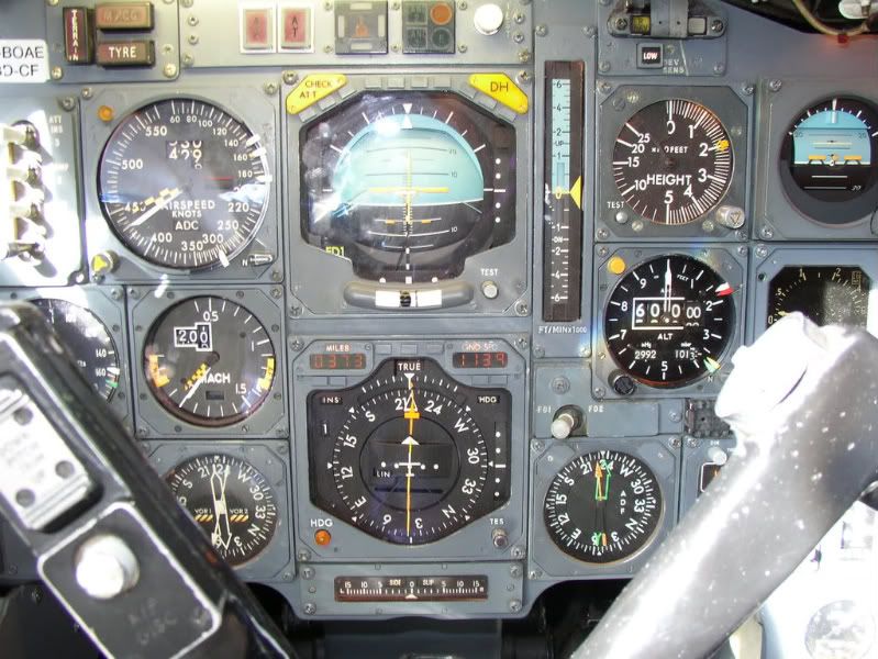
The available IAS speed range is shown on the ASI, and lies between the yellow and black Barbers Pole, currently indicating 440kts, and the white bug set to 300kts, the VLA ( L owest A uthorised speed) at this altitude.
The available Mach speed range is shown on the Mach meter, and lies between the yellow and black Barbers Pole, currently indicating M2.05, and the yellow bug which indicates the lowest Mach number allowed for the current aircraft CG position (the AFT limit) currently showing M1.35.
So, given that at her maximum altitude she had a speed range of 140kts IAS and a Mach range of M0.7, we can see that coffin corner was not a problem!
main_dog
...I too would like to ask what her idle thrust glide ratio was...
By my calculations, the figures quoted for a straight in approach, give an average glide ratio of around 20:1, however these were for a standard decel/descent, and on Concorde the early part of the decel/descent was not flown at idle power.
A considerable amount of power was left on initially, around 94% N2, for various reasons, and only below M1.0 were the throttles usually selected to idle.
I hadn’t noticed it until now but there does not appear to have been a chart giving glide distance at idle thrust!
However, since the speeds to be flown during the “4 Eng Flame Out” procedure were not too far from the normal decel/descent speeds, I’ll hazard a guess (and that is all it is) that the glide distance from FL600, with no thrust, would have been about 150nm, giving a glide ratio of around 15:1.
Subjects
Airbus
Barbados
British Airways
C of G
Captains
FL600
G-BOAE
Glide
IAS (Indicated Air Speed)
Links are to this post in the relevant subject page so that this post can be seen in context.
Reply to this quoting this original post. You need to be logged in. Not available on closed threads.
August 23, 2010, 11:59:00 GMT
permalink Post: 5887244
...I have noticed...Application of take-off thrust is done by slamming the throttles forward rather than the traditional ease them up method used on most other aircraft...Why...
It does seem rather brutal at first glance doesn't it, especially if you are used to handling piston engines with care!
Firstly however, unlike most jet aircraft, you never set reduced thrust for take-off but always set full power, which on Concorde meant that the throttles had to be fully forward, as far as they would go.
Secondly, you were not actually controlling the engines as directly as you might think. Various control units between the throttles and the engines would electronically regulate everything for you, especially spool-up rates, temperatures and thrust levels, even keeping #4 eng throttled back initially to 88% until reaching 60kts.
In effect, you were really just operating a switch telling the computers to set full take-off power.
And how slowly do you turn on a switch?
Subjects
Take-off Thrust
Links are to this post in the relevant subject page so that this post can be seen in context.
Reply to this quoting this original post. You need to be logged in. Not available on closed threads.
August 24, 2010, 23:38:00 GMT
permalink Post: 5890435
...The Max Climb/Max Cruise AFCS mode combo is a mode like no other that I've personally seen before or since anywhere...
True.
On descent, with the throttles at idle, it also worked beautifully as a MAX DESC mode
It was a very versatile mode.

Best Regards
Bellerophon
Subjects
AFCS (Automtic Flight Control System)
Links are to this post in the relevant subject page so that this post can be seen in context.
Reply to this quoting this original post. You need to be logged in. Not available on closed threads.
August 25, 2010, 12:34:00 GMT
permalink Post: 5891320
...In your superb photograph ... thank you ... both RMI'S shown seem to be showing a heading of 230 while the heading on the HSI shows 220 with the annunciation TRUE above the HSI...I am thinking that the RMI's are showing magnetic headings ?...
Correct. The RMIs show 230\xb0(M) and the HSI shows 220\xb0(T).
...were you operating on TRUE headings in this case as it seems...
Yes.
The HSI had earlier been selected to show TRUE data, by moving the RAD/INS switch (out of picture) to INS. This changed the data inputs to the HSI from Magnetic to True, but did not affect the data input to the RMI compass cards. The data input to the RMIs was always magnetic, supplied by one of two compass systems; normally #2 compass system fed the Captain\x92s RMI card.
The red/black flags visible in the VOR RMI indicate that both the VOR stations selected are out of range.
The flags visible on the HSI indicate:
-
TRUE.......True compass data (not magnetic) is being displayed. (TRUE/MAG)
-
INS..........An INS (not a VOR) is supplying Nav data to this HSI. (INS/RAD)
-
1............#1 INS (not #2) is supplying Nav data to this HSI. (1/2)
-
HDG.........The steering index shows selected heading (not track). (HDG/TRK)
- LIN...........The beam bar is displaying linear (not angular) displacement. (LIN/ANG)
... what was the reason for this ?...
When flying long legs over areas of the world with few/no radio facilities, aircraft generally navigate from one Lat/Long waypoint to the next Lat/Long waypoint by using their INS systems, rather than tracking from radio beacon to radio beacon. The North Atlantic Track system is good example of this, as is this route down to BGI. Because there is no useful magnetic/radio information to display in such areas, True (INS) information is usually displayed, which brings with it two main advantages.
Firstly, you get to monitor how well the autopilot is doing, because the beam bar in the HSI should always be centralised if the aircraft is on track.
Secondly, as the aircraft changes course over a waypoint, you get the chance to check the Initial True Track it then takes up corresponds to the ITT pre-calculated on your flight plan. This is an important check (called the \x93Waypoint Change Drill\x94) in BA, that you have not mis-programmed the INS waypoints!
This procedure, of navigating in True, is by no means a Concorde procedure, all long range BA aircraft utilise it, and it is in common use in most airlines and aircraft flying long range routes around the World.
Best Regards
Bellerophon
Last edited by Bellerophon; 25th August 2010 at 22:01 .
Subjects
Auto-pilot
British Airways
INS (Inertial Navigation System)
Links are to this post in the relevant subject page so that this post can be seen in context.
Reply to this quoting this original post. You need to be logged in. Not available on closed threads.
August 31, 2010, 01:25:00 GMT
permalink Post: 5902857
...I just wondered how the engine was kept at a sub idle 30% N2?...
Just below each engine's individual start switch, there was a second switch, which would select the type of start required, either NORMAL or DEBOW.
When between ten minutes and five hours had elapsed since an engine was last run, a debow start was required. With a debow start selected, the engine was started normally, but the debow system automatically stabilised the engine at a sub-idle RPM, around 30% N2, whilst the interior engine temperatures became more uniform and the HP spool shaft re-aligned/straightened itself.
As to exactly how it did this, you're going to need a reply from an engineer not a pilot. As far as we were concerned, it was the PFM box in the engine start system!
After running for one minute stabilised in debow (or when the debow light came on) the F/E would return the debow switch to normal and check that the N2 returned to idle and the debow light went out. The F/E would monitor the N2 very carefully over these few seconds, as the engine came out of debow, to check that the engine cleared rotating stall.
If it didn't, two things would happen.
Firstly the F/E got fairly busy, trying to clear the engine out of rotating stall without causing it to surge, and secondly, as with any Concorde engine malfunction drill, I quietly give thanks that I was a pilot and not a F/E.
If a debow start was required, but somehow got missed, the engine could give a reasonable impression of an out-of-balance tumble drier, or so I'm told.
Best Regards
Bellerophon
Subjects
Engine surge
Rotating (engine) Stall
Links are to this post in the relevant subject page so that this post can be seen in context.
Reply to this quoting this original post. You need to be logged in. Not available on closed threads.
September 03, 2010, 20:48:00 GMT
permalink Post: 5911995
... I think am right to assume there were no spoilers...
Correct.
...so on landing did the act of bring the nose down spoil the lift...
Yes, as with most conventional aircraft, reducing the aircraft pitch attitude (once the main wheels were on the runway) would reduce the angle-of-attack and therefore reduce the amount of lift being generated by the wing. Modern aircraft wings are very efficient and will still be generating a considerable amount of lift during the landing roll, even as the aircraft slows down.
Put simply, spoilers and/or lift dump systems are required to destroy this lift, in order to get as much of the aircraft weight as possible on the main landing gear, which, in turn, allows greater pressure to be applied to the wheel brakes before the wheels start to lock-up and the anti-skid units activate to release the applied brake pressure.
Concorde\x92s wing however developed very little lift at zero pitch attitude, so, once you had landed the nose wheel, there was no need for spoilers.
...is that the reason why the non flying pilot pushed the yolk forward once she was down?...
No.
The reason was that using reverse thrust on the ground on Concorde caused a nose-up pitch tendency, strong enough to lift the nose. The procedure was the handling pilot would call Stick Forward as soon as she had landed the nose wheel and the NHP would apply forward pressure on the control column to make sure the nose didn\x92t rise.
If the handling pilot applied reverse thrust before the nose wheel was on the ground, things could get very awkward very quickly.
Firstly, the nose would probably rise, quite possibly beyond the power of the control column to lower it. Secondly, the wing would still be generating (some) lift and so only reduced wheel braking would be available before the anti-skids kicked in, and the amount of runway left would be diminishing faster than normal.
The solution was to reduce to Reverse Idle power until the nose wheel was back on the runway, however, in the heat of the moment it was very easy to go through Reverse Idle and on into Forward Idle. Not only would this again hinder the deceleration of the aircraft, but it would also run the risk of scraping the reverser buckets on the runway (as the buckets moved from the reverse thrust position to the forward thrust position) so tight were the clearances between the buckets and the runway on landing.
Best Regards
Bellerophon
Subjects
Anti-skid
Braking
Landing Gear
Reverse Thrust
Thrust Reversers
Links are to this post in the relevant subject page so that this post can be seen in context.
Reply to this quoting this original post. You need to be logged in. Not available on closed threads.
September 03, 2010, 22:17:00 GMT
permalink Post: 5912171
Yes, as Brit312 has suggested, the pitch change as Concorde entered ground effect on landing was nose down.
In simple terms (i.e. as it was explained to me
) due to the nose up approach attitude, (10\xbd\xb0 PA) the wider trailing edge of the wing entered ground effect before the much narrower leading edge of the wing, meaning more lift was now being generated at the rear of the wing than before, aft of the CG, resulting in a nose down pitch change.
As you say, she landed at (or very nearly at) her approach attitude, with ground effect responsible for killing most of the rate of descent, but, during the last fifty feet or so, in order to maintain that steady pitch attitude against the increasing nose down pitch change, a definite, progressive, rearward movement of the control column was required, a movement that felt remarkably like a \x93flare\x94 to the pilot.
The available pitch attitude range on landing was very tight. Depending on the approach speed selected, touchdown attitude typically would be 11\xb0 - 11\xbd\xb0, with a warning call of \x93Attitude\x94 from the NHP at 12\xbd\xb0 PA. On Concorde, effectively you only got one attempt at making a good landing, after that, with little room to manoeuvre (literally), you had to settle for a safe one, by making sure the wings were level, the rate of descent reasonable, and the pitch attitude within limits and just accepting whatever sort of touchdown she gave you!
The speed, pitch and tone of the F/E's voice, as he made the radio height calls, were as reliable an indication as any as to what sort of arrival was imminent!
Best Regards
Bellerophon
Subjects
C of G
Links are to this post in the relevant subject page so that this post can be seen in context.
Reply to this quoting this original post. You need to be logged in. Not available on closed threads.
September 06, 2010, 12:52:00 GMT
permalink Post: 5917084
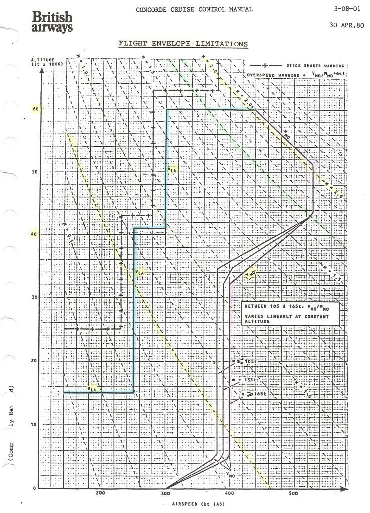
Is this what you're looking for?
Best Regards
Bellerophon
Subjects
Flight Envelope
Links are to this post in the relevant subject page so that this post can be seen in context.
Reply to this quoting this original post. You need to be logged in. Not available on closed threads.
September 06, 2010, 22:18:00 GMT
permalink Post: 5918330
Following the excellent explanation given by ChristiaanJ about the relationships between OAT, Mach number, TAS and IAS (which I have now copied and shall shamelessly pass off as my own work in future
) if you wish to see how these relationships work in practice you might look back at the photo posted at reply #66.
You will see that at FL600 the aircraft had a GS of 1,139 kts whilst flying at M2.00 and an IAS of 429 kts.
We don\x92t know what the wind was, nor what the TAS or OAT were, but we can easily deduce that:
- If the OAT was standard at FL600, at -56.5\xb0C, then, as at that temperature M2.00 equates to 1,147 kts TAS, in order to have a GS of 1,139 kts, she must have been flying into an 8 kt headwind.
- If the wind at that altitude was calm, then her GS of 1,139 kts must have been the same as her TAS. For M2.00 to be 1,139 kts TAS, then the temperature at FL600 must have been 3\xb0C colder than standard, at -59.5\xb0C.
- If , as was typical on a LHR-BGI sector, the OAT at FL600 was 10\xb0C colder than standard, at -66.5\xb0C, then M2.00 would equate to 1,120 kts TAS, so to have a GS of 1,139 kts, she must have been flying in a 19 kt tailwind.
For obtaining Mach/TAS/Temp values quickly and easily, as well as other useful information on the atmosphere, this Standard Atmosphere Calculator website is extremely useful.
Best Regards
Bellerophon
Subjects
FL600
IAS (Indicated Air Speed)
LHR-BGI Route
TAS (True Air Speed)
Links are to this post in the relevant subject page so that this post can be seen in context.
Reply to this quoting this original post. You need to be logged in. Not available on closed threads.
September 07, 2010, 17:55:00 GMT
permalink Post: 5920067
...In fact quite a bit was transferred from previous aircraft designs to Concorde...
Indeed; I've heard it said that the Concorde nose & visor selector lever:
came out of the spare parts box, it certainly looks similar to the Bristol Britannia flap selector lever (rear right hand corner of centre console):
Best Regards
Bellerophon
Subjects
Visor
Links are to this post in the relevant subject page so that this post can be seen in context.
Reply to this quoting this original post. You need to be logged in. Not available on closed threads.
September 13, 2010, 13:13:00 GMT
permalink Post: 5931934
They were always fascinating to listen to, and provided an intriguing insight into a design world, now long gone, inhabited by engineers and draughtsmen armed with slide rules, drawing boards and blueprints. As ever, with people of real ability, they tended to talk more about their few failures rather than their many successes, often in the most amusing and self deprecating terms. It is their stories which really ought to be preserved, although it is not for us, even now, to relate some of their tales, told to us with a chuckle, but in strict confidence!
Suffice to say that the senior fire officer who misread litres-per-minute as gallons-per-minute during an Olympus water ingestion test probably would not want any further publicity, likewise the apprentice who didn\x92t defrost the chicken before firing it into an engine running at full power in the bird ingestion test. My favourite was the supersonic hailstone story, fired as part of a hailstone ingestion test, but with uncertain results, the final resting place of said hailstone still being slightly obscure to this day. If anyone in the greater Bristol area got hit by a particularly hard snowball in the early sixties, the Filton test engineers are very sorry, and would like to apologise!
However, it is often the little insights into the past that amuse one the most and stick in one\x92s mind. During one such conversation, with a couple of thermodynamicists, I ventured to ask how they had settled on the (rather difficult to memorise) various temperature limits associated with Concorde.
For instance, why a nose temperature limit of +127\xb0C, why not +130\xb0C, much easier for a pilot to remember?
\x93Isn\x92t it obvious?\x94 one replied politely, genuinely puzzled by my question.
\x93Computer generation\x94 replied his colleague to him, pointing his pipe stem at me.
\x93Ah yes\x94 said the first, \x93that would be it\x94.
They then went on to explain, in ever such a kindly manner, that, in thermodynamics, apparently the square, and the square root, of the absolute temperature of a material are terms used in many equations. Being armed mostly only with slide rules (and as they were in the vicinity of 120\xb0C to 130\xb0C as a limit anyway) it had been decided to make life easy and settle on +127\xb0C as the limit, a temperature for which they could easily calculate the square and square root in their heads.
Noticing my bewilderment at the thought that anyone might be able to calculate the square or the square root of 127 in their heads, they proceeded to explain it to me still further, very slowly; in the manner that one would speak to an aged and rather deaf great aunt!
\x95 Max Nose temp = +127\xb0C equal to 400K
\x95 √400 = 20
\x95 400\xb2 = 160,000.
Best Regards
Bellerophon
Subjects
Conversion Course
Filton
Links are to this post in the relevant subject page so that this post can be seen in context.
Reply to this quoting this original post. You need to be logged in. Not available on closed threads.
September 19, 2010, 11:40:00 GMT
permalink Post: 5943311
... Haynes' book on page 23, says about an increased MLW of 130 tons instead of the famous 111,13 (sic) tons. I NEVER, ever, heard/read about this, can anyone shine a light on it?...
I'm not aware of what Haynes may say about Concorde - I don't have a copy of the book and haven't read it - however it is well documented that landings at weights up to 130,000 kgs were permitted on Concorde, provided various conditions were met.
It was a Conditional Procedure called Fuel Saving Landing .
BA did not plan flights to land at 130,000 kgs but the procedure was available for use when required.
In practice it was rarely used, and the occasions on which it was used tended to be following a return to the departure airfield, or a diversion in the early part of the flight, with the aircraft still above the (normal) maximum landing weight, in order to reduce the amount of fuel to be jettisoned.
Best Regards
Bellerophon
Subjects
British Airways
Fuel Saving Landing
Haynes guide to Concorde
Links are to this post in the relevant subject page so that this post can be seen in context.
Reply to this quoting this original post. You need to be logged in. Not available on closed threads.
October 11, 2010, 18:59:00 GMT
permalink Post: 5988352
... on shorter charter flights was there a mininium ammount of fuel that had to be loaded just to always have enough fuel for CofG movement...
Yes, 35,000 kgs, at take-off, for a short supersonic flight. This would allow sufficient fuel to be transferred rearwards in order to achieve a CG approaching 59%.
If the flight was to remain subsonic, the fuel figure dropped to 25,000 kgs, as the required CG for subsonic cruise was 55% not 59%.
Both these figures were at take-off, so the estimated taxy fuel had to be added to these figures in order to arrive at the minimum fuel figure required to be loaded.
...was it possible to be in a position where trip fuel, fuel to an alternate etc was less than the fuel required for CofG movement after take off?...
No, at least it should not have been!
However, a situation was sometimes reached in flight, generally only towards the end of the planned supercruise portion of a LHR-BGI sector, where, with the aircraft at M2.00 and FL600, it was no longer possible to maintain a CG of 59%, as the "ballast" fuel, which had been transferred aft into tank 11, was now required forward again as "fuel" fuel, to top up other tanks which had reached their minimum permitted levels.
In this case, once the forward transfer of fuel had begun, the CG would also be slowly moving FWD, and one would be compelled to commence the decel and descent earlier than desired, something EXWOK touched on here much earlier in this thread.
Best Regards
Bellerophon
Last edited by Bellerophon; 11th October 2010 at 22:17 .
Subjects
C of G
FL600
LHR-BGI Route
Super-cruise
Links are to this post in the relevant subject page so that this post can be seen in context.
Reply to this quoting this original post. You need to be logged in. Not available on closed threads.
October 11, 2010, 22:13:00 GMT
permalink Post: 5988779
...As an ATCO we had very specific instructions about how to deal with a Concord(e) radiation overdose. We were told that it would have to make an emergency descent and how to integrate it with other traffic as it descended and what the priorities were...
The display, on the radiation meter, was divided into three, coloured, sections.
\x95 AMBER ....11\x9650 millirems/hour....Alert ATC, prepare for possible descent.
\x95 RED ........51+....millirems/hour.....Descend out of high dosage flight levels.
The procedure to be followed was simply an Abnormal Procedure rather than an Emergency Drill .
\x95 RED .........Alert ATC, obtain clearance, and then descend.
It was of some concern that the sort of radiation levels that would trigger the radiation alarm might very well also be playing havoc with radio communications, particularly HF communications. The possibility of being unable to communicate with ATC was one that had to be considered, and so it was only under these circumstances, with both a Red MWS RADN warning and an ATC communications failure, that the Captain was permitted, at his discretion, to perform an uncleared descent.
It's comforting to know that you were prepared to deal with us if required, but unlikely, I would have thought, that your services would have been called upon in practice.
...Has any Concord crew ever had to do this?...
I not aware of any such descent incident, although obviously I can\x92t state definitely that one never occurred.
It wasn't unknown for the radiation alarm to go off, I\x92ve had it, briefly, twice, both times at lowish level over the sea on departure from JFK. On one occasion there was nothing at all to indicate what might have caused it, on the other, we had just overflown a rather large waste barge being towed somewhere!
Best Regards
Bellerophon
Subjects
Captains
Depressurisation
JFK
Radiation Exposure
Links are to this post in the relevant subject page so that this post can be seen in context.
Reply to this quoting this original post. You need to be logged in. Not available on closed threads.
October 27, 2010, 23:05:00 GMT
permalink Post: 6021738
...Did you need all 4 reheats to go from 0.95 - 1.7 ?...
No.
Two reheats were the minimum for transonic acceleration, however due regard would have to paid to the additional fuel usage with one or two reheats failed.
...If you got to 1.3 and then one or more failed could you continue (albeit with slower acceleration ?)...
Yes, as above, whilst remembering the 15 minute time limit on the use of reheat.
...I presume if you were unable to get the things lit at 0.95 you just turned round and went home again ?...
Yes, once you were convinced that at least three were not going to light up.
...The procedure would take around 90 mins so would you need to burn off fuel or already be at acceptable landing weight by that time ?...
Not something I ever had to do, fortunately, but even so, 90 minutes would seem somewhat excessive to me, given that the aircraft would still have been over the Bristol channel. On a transatlantic sector, fuel jettisoning would have been necessary to get down to 130,000 kgs (for a fuel saving landing) or 111,130 kgs (MLW) if the nature of the failure precluded a fuel saving landing.
...once when aboard at about 50K-55K feet the aircraft rolled I would estimate 3 degrees to the left and then came back level again almost immediately...what might have cause such an event (I would guess an airflow issue with intake or engine ?)...
Any number of things could have caused this, but probably the most likely one is the one you suspected, a (transient) intake problem.
Best Regards
Bellerophon
Subjects
Afterburner/Re-heat
Fuel Saving Landing
Intakes
Transonic Acceleration
Links are to this post in the relevant subject page so that this post can be seen in context.
Reply to this quoting this original post. You need to be logged in. Not available on closed threads.
October 30, 2010, 12:46:00 GMT
permalink Post: 6027195
Requirements :
- Manual landing, at V REF , only
- Minimum of one autothrottle operative at start of approach
- Contingency power available
- Specific fuel distribution achieved
- Record in Maintenance Log
Not permitted with :
- Slippery runway
- Precipitation covered runway
- 3-engine ferry
- 2-engine approach and landing
- Reduced noise approach
- Fuelled with wide-cut fuel
- Secondary nozzle locked out
- Brake unit isolated
- Total loss of Electric Trim
- Total loss of Pitch Stab
- Total loss of Electrical Signalling
- Suspected tyre failure
Notes
3-engine landings were permitted. For all landings the landing gear would be lowered earlier than normal to ensure the brakes were stone cold to start with, maximum reverse thrust would be used on landing, and braking modulated so as to use (nearly) all of the full length of the runway. Landing performance figures at 130,000 kgs were in the performance manual for most runways. Any runway for which this procedure had not been pre-authorised required some rather tedious calculations, using the generalised basic data and graphs found in the performance manual.
If manual performance calculations were necessary, the F/E and I usually seemed to find that another problem that required our urgent and undivided attention had come up, and we would reluctantly be compelled to hand over all the manuals, charts and graphs for the F/O to perform the calculations!
If the aircraft had an AFT ZFW CG (perhaps loaded with a lot of heavy bags in the rear hold), and given the specific fuel distribution requirements for a fuel saving landing, it was possible that the landing weight might have to be reduced below 130,000 kgs, in order to achieve a landing CG of 53.5%.
After landing, record the actual landing weight in the Maintenance Log using code 2899XXOO, sign it, and then leg it swiftly, to avoid M2Dude and the boys, who somehow always managed to imply that you were responsible for anything that had gone wrong with their pride and joy since they last handed her over to you!

Reasons
The clue is in the name! A possible saving of roughly 5,200 gallons of fuel, nearly 19,000 kgs, which need not be jettisoned, thus reducing the time spent in the air before re-landing, fuel costs and pollution.
Best Regards
Bellerophon
Subjects
Auto-throttle
Braking
C of G
Fuel Saving Landing
Landing Gear
Manuals
Nozzles
Reverse Thrust
Trim
Links are to this post in the relevant subject page so that this post can be seen in context.
Reply to this quoting this original post. You need to be logged in. Not available on closed threads.
November 25, 2010, 21:00:00 GMT
permalink Post: 6084330
... Am I right in assuming that TLA stands for throttle lever angle? ...
Yes. TLA was a TLA for throttle lever angle.
... did setting the throttles to a certain angle then give a known thrust setting? ...
Yes, the calculated thrust required at the noise abatement point. The TLA was calculated by the NHP (as part of the take-off performance calculations) and later cross-checked by the Captain and F/E.
I don\x92t know whether it is audible on the DVD, but the checklist question was \x93Clock and TLA bugs\x94 .
If not already set, the Captain and F/O would set the noise abatement time on their respective (countdown) clocks and the F/E would cross-checked them, and, if not already set, the F/E would set the TLA bugs (on an engraved scale on either side of the throttle quadrant) to the noise abatement setting and the Captain and F/O would cross-check him.
The checklist response was \x94Set\x94 .
Best Regards
Bellerophon
Subjects
Captains
Checklists
Noise Abatement
TLA (Throttle Lever Angle)
Links are to this post in the relevant subject page so that this post can be seen in context.
Reply to this quoting this original post. You need to be logged in. Not available on closed threads.
November 25, 2010, 21:41:00 GMT
permalink Post: 6084404

Best Regards
Bellerophon
Subjects: None
No recorded likes for this post (could be before pprune supported 'likes').Reply to this quoting this original post. You need to be logged in. Not available on closed threads.
December 03, 2010, 13:37:00 GMT
permalink Post: 6099796
Deciding that they would like to maintain this groundspeed, they went ALT HOLD and MACH HOLD at around FL530. They maintained their groundspeed, so the story goes, but the autothrottle then progressively reduced the N1, as the aircraft weight reduced, over the next couple of hours, into the prohibited range!
Did you ever hear of any such event?
Best Regards
Bellerophon
Subjects
ALT HOLD
Auto-throttle
Intakes
N1 (revolutions)
Olympus 593
Links are to this post in the relevant subject page so that this post can be seen in context.
Reply to this quoting this original post. You need to be logged in. Not available on closed threads.