August 15, 2010, 15:54:00 GMT
permalink Post: 5871342
I've read "By the Rivers of Babylon" too..... and there is some fact behind the fiction.
History does not relate if and where the El Al Concordes would have had APUs.
However, history DOES relate, that the two Concordes ordered by Iran Air WOULD have had APUs (which would have made sense in the Middle East).
Now, Iran Air was the very last company to cancel its orders, and by the time they did, Concorde 214 (now G-BOAG) and 216 (now G-BOAF) were already well underway (they ended up flying initially as white tails).
As a result, both 214 and 216 still have the mounting holes and fittings for an APU. Don't ask me where, but experts know where to find them to this day....
Subjects
APU (Auxiliary Power Unit)
Auxiliary Power Unit
By the Rivers of Babylon
G-BOAF
G-BOAG
Links are to this post in the relevant subject page so that this post can be seen in context.
Reply to this quoting this original post. You need to be logged in. Not available on closed threads.
August 16, 2010, 15:18:00 GMT
permalink Post: 5873329
I can try asking around, but can't remember my original source - it probably came up during a discussion of the MEPU on Delta Golf or on 01 several years ago. I very much doubt it would be mentioned explicitly in the SRM (Structural Repair Manual).
IIRC the MEPU lived in the tail (I'll look it up), so it's not impossible the APU was planned in the same location.
Subjects
APU (Auxiliary Power Unit)
G-BBDG
MEPU (Monogol Emergency Power Unit)
Links are to this post in the relevant subject page so that this post can be seen in context.
Reply to this quoting this original post. You need to be logged in. Not available on closed threads.
August 16, 2010, 16:37:00 GMT
permalink Post: 5873511
In the meantime, here's the MEPU exhaust in the tailcone of Delta Golf, courtesy of Neil Walker.
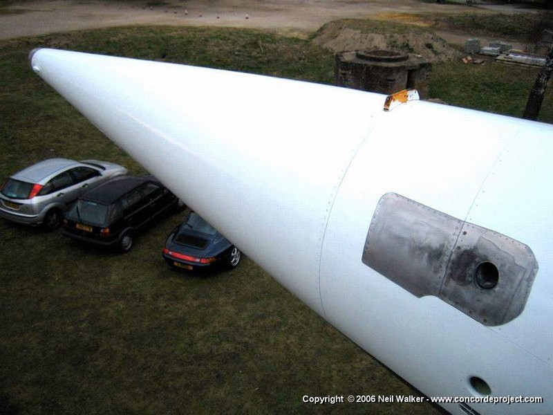
CJ
Subjects
G-BBDG
MEPU (Monogol Emergency Power Unit)
Tail Cone
Links are to this post in the relevant subject page so that this post can be seen in context.
Reply to this quoting this original post. You need to be logged in. Not available on closed threads.
August 16, 2010, 19:53:00 GMT
permalink Post: 5873899
Subjects
G-AXDN
Links are to this post in the relevant subject page so that this post can be seen in context.
Reply to this quoting this original post. You need to be logged in. Not available on closed threads.
August 17, 2010, 14:33:00 GMT
permalink Post: 5875273
Nice set of photos of "The Thing" here :
MEPU at MAE at le Bourget .
This one is at the Air and Space Museum at Le Bourget, near Paris. My guess is that is was a spare, since the manufacturing date is 1973. 'SA flew in January '73 and 'SB in December '73.
IIRC, Delta Golf arrived at Brooklands with the MEPU still in place; I might have a photo.
As to the installation, we're obviously thinking along the same lines....
However, there were already several conduits through tank 11, such as hydraulics for the tail wheel, various electrics, and the 'backbone' fuel manifolds, that ended at the fuel jettison port in the tailcone.
A couple of fairly substantial air ducts would only have displaced a few hundred kgs of fuel at the most, out of the more than 10,000 kgs in tank 11.
And yes, of course, the whole point of the APU would be to have independent ground start and ground airco available, so clearly an APU would have been bigger and heavier than the MEPU (which was only just over 80 lbs), plus the problem of the air intake and bigger exhaust.
I'd have to get the drawings out to see how easy or difficult it would have been to fit one in the available space.
Since the tailcone was BAC, and both 214 and 216 were built at Filton, I wonder if anybody there still remembers?
Subjects
APU (Auxiliary Power Unit)
Brooklands
Filton
G-BBDG
G-BOAF
G-BOAG
Intakes
Le Bourget
MEPU (Monogol Emergency Power Unit)
Tail Cone
Links are to this post in the relevant subject page so that this post can be seen in context.
Reply to this quoting this original post. You need to be logged in. Not available on closed threads.
August 18, 2010, 21:24:00 GMT
permalink Post: 5878555
Re the MEPU at the Le Bourget museum...
The story I just got was that it was taken off F-WTSA or F-WTSB at Roissy for a fault and replaced (both 'SA and 'SB operated out of Roissy around '74 / '75 for things like route proving, etc.).
It got left on a shelf in a store, and was only discovered again in 2003 during the "big clean-out" and was saved 'in extremis' by somebody who recognised it for what it was, stopped it from being 'binned' and took it over to the museum.
So yes, you're right, essentially all of it was "useable" fuel, it did not serve only for the trim.
Jock Lowe seems to have stated there is a photo.... and we all still wonder if there is some footage taken from the Lear Jet during the filming of "Airport 79". But none is publicly known to exist ... we just know it's been done!
Subjects
F-WTSA
F-WTSB
Le Bourget
MEPU (Monogol Emergency Power Unit)
Trim
Links are to this post in the relevant subject page so that this post can be seen in context.
Reply to this quoting this original post. You need to be logged in. Not available on closed threads.
August 18, 2010, 22:19:00 GMT
permalink Post: 5878654
Thnks for the headup... I still have to get that book into my little library.
I've seen that quote before.
Dr. Hooker was right of course.
I think we'll never know what Iran Air's reasoning was......
Even with the vastly inferior infrastructucture in the Middle East at the time, it would seem to me it would have been much cheaper to station enough GPUs and ASUs at their various destinations (only two aircraft, after all), rather than go for an airline-specific APU fit.
Subjects
APU (Auxiliary Power Unit)
Ground Power Unit
Sir Stanley Hooker
Links are to this post in the relevant subject page so that this post can be seen in context.
Reply to this quoting this original post. You need to be logged in. Not available on closed threads.
August 19, 2010, 14:37:00 GMT
permalink Post: 5880031
To complement M2dude's notes re nose and visor:
There were basically four 'positions':
Nose and visor up (supersonic),
Nose up, visor down only (subsonic climd and descent),
Nose down 5\xb0, visor down (take-off and initial climb),
Nose down 12.5\xb0, visor down (approach and landing).
Normally nose and visor are raised and lowered by the green hydraulic system (as is done until today on F-BTSD at Le Bourget).
In 'standby' mode, the visor was lowered by the yellow hydraulic system.
Then the nose uplocks were released by the yellow system, and the nose would free-fall to the 5\xb0 position.
Another switch allowed to hydraulically release the 5\xb0 downlocks, and the nose would free-fall again, now to the 12.5\xb0 psition.
In this 'standby' mode, the nose and visor could not be raised again.
In the best "belt, braces AND a piece of string" tradition of Concorde, if both the 'normal' and 'standby' system failed, there was a big handle on the F/O side of the central pedestal.
This released the nose uplocks manually, the nose would start to free-fall, automatically unlocking the visor, and both would then free-fall down: the nose only to the 5\xb0 position.
To complete the story... there is a 5th position: nose 17.5\xb0 down!
This was the 'nose fully down' position as designed originally and installed on 001 and 002.
It met with sharp criticism from the test pilots, because of the lack of a forward visual reference with the nose fully down. "It's like looking over the edge of a cliff", was the unanimous comment of the pilots.
So a couple of mechanical stops were added that limited the 'nose down' angle to 12.5\xb0.
But the basic design of the nose was not changed otherwise, so even on the production aircraft the nose could be lowered to 17.5\xb0, but only in the hangar, by removing the mechanical stops. It may have been done a few times, for better access to the visor and nose mechanism.
Minor anecdote... the nose and visor were up during supersonic flight, of course, but also when the aircraft were on the ground and parked outside, simply to keep the rain and dirt out.
But... the prototypes had a metal visor, with two tiny windows, and it was inconveniently dark on the ground in the cockpit with the visor up . So on the ground we always kept the visor down, unless the aircraft was parked outside for any length of time.
Subjects
F-BTSD
Hydraulic
Hydraulic System - YELLOW
Le Bourget
Visor
Links are to this post in the relevant subject page so that this post can be seen in context.
Reply to this quoting this original post. You need to be logged in. Not available on closed threads.
August 20, 2010, 00:05:00 GMT
permalink Post: 5880916
"Friction" is the "easy explanation", but not really true.
It was due to the air being compressed , being "pushed sideways" by the aircraft trying to make its way through the air at Mach 2, if you like
Same as what happens in a bicycle pump, that get hot as you compress the air. The analogy is somewhat oversimplified, but the phenomenon is the same.
The hottest spots were actually the nose and the wing leading edge, not because of friction, but because that's where the air was locally brought to a total standstill, hence compressed the most. Temperature there could rise to +127\xb0C, from the -50\xb0C and less of the air at 50,000ft just ahead.
"How was this differential expansion dealt with?"
Mostly by attaching things like equipment racks (think of the hat) and floors, and other bits and pieces, to the outer fuselage structure only at one end, and making sure they could move relative to the outer structure when it expanded.
Hope that explains it?
Subjects
Expansion
Links are to this post in the relevant subject page so that this post can be seen in context.
Reply to this quoting this original post. You need to be logged in. Not available on closed threads.
August 20, 2010, 00:22:00 GMT
permalink Post: 5880940
We are looking at two 4 inch diameter ducts, the same that are still used to this day on aircraft such as the B777.
One for the air start turbine, which was driven at about 45 psi nominal by the same kind of ASUs (Air Start Units) as are still in use today.
The other for the aircon... not to be confused with the huge near-ambient pressure hoses that were connected directly to the cabin, rather than to the aircon packs.
Subjects
APU (Auxiliary Power Unit)
Links are to this post in the relevant subject page so that this post can be seen in context.
Reply to this quoting this original post. You need to be logged in. Not available on closed threads.
August 20, 2010, 11:44:00 GMT
permalink Post: 5881833
The gears retracted inwards, and when up, the bogies were right next to each other on each side of the keel. As a matter of fact, the main gear legs had to be "shortened" while they retracted, otherwise they wouldn't even have fitted...
Subjects
Expansion
Hydraulic
Landing Gear
Trim
Links are to this post in the relevant subject page so that this post can be seen in context.
Reply to this quoting this original post. You need to be logged in. Not available on closed threads.
August 20, 2010, 22:55:00 GMT
permalink Post: 5883024

As an example in my particular field, you have to be an expert to distinguish the Concorde ADI (Attitude Director Indicator) and HSI (Horizontal Situation Indicator) - the two big central instruments on the pilot's and copilot's panel - from those on the first Airbus, the A300, or the early A310s. Apart from a couple of lights and buttons, they were the same, and the innards were pretty well identical.
And a lot of the technology in the AFCS (Automtic Flight Control System, i.e., the autopilots, etc.) was also virtually indistinguishable (the circuitry was obviously different... an A300 did not do Mach2).
But even more than the technical foundations, Concorde also laid the foundations for an effective and successful international cooperation in aircraft design, development and production.
We learned a tremendous amount from Concorde... Airbus might still have happened without Concorde, but it certainly would have happened years later.
The one difference with "modern" FBW commercial planes (such as the A320) is that Concorde still did have a mechanical back-up for when all else failed.
At the time, there was still a doubt about all these new-fangled elektriks replacing good old rods and cables, so when you look under the floor in a Concorde, the rods and cables are still there.
But apart from tests and training for emergencies, essentially they were never used.
Subjects
AFCS (Automtic Flight Control System)
Airbus
FBW (Fly By Wire)
Links are to this post in the relevant subject page so that this post can be seen in context.
Reply to this quoting this original post. You need to be logged in. Not available on closed threads.
August 20, 2010, 23:21:00 GMT
permalink Post: 5883057
As far as the APU ducting issue goes (hee, hee, not often we disagree Christiaan
 ) we are just going to have to agree to disagee about this, although I accept that two 4" diameter pipes (PLUS THERMAL INSULATION) might have done it, BUT I still stand by the other points.

So I happily agree to disagree on the rest... between the two of us, each looking at our own clues, and with the help of anybody else who has more info, we might still find the answer!
One thought I had... with an APU in the forward baggage hold, you'd also have to take the air intake and exhaust through the pressure hull, and provide sound and thermal insulation for the entire APU itself.
From a design point of view, I'd have gone for the same location of the earlier pseudo-APU (the MEPU), and then solved the remaining problems from that starting point.
Subjects
APU (Auxiliary Power Unit)
G-BOAF
G-BOAG
Intakes
MEPU (Monogol Emergency Power Unit)
Links are to this post in the relevant subject page so that this post can be seen in context.
Reply to this quoting this original post. You need to be logged in. Not available on closed threads.
August 21, 2010, 15:12:00 GMT
permalink Post: 5884081
I would say those books already have been written... from the autobiographies of Turcat and Trubshaw, through the books by people like Brian Calvert, Christopher Orlebar and others, to the Haynes "Concorde Owners' Workshop Manual" (!), that's come out recently.
I've written some bits and pieces, but it's more for my offspring, to explain what all that Concorde junk and documentation in the shed is all about, so they don't all thrash it when I'm gone... I don't think my story would interest a larger public.
As M2dude says, we just like to share some of our experiences with those who are interested.
Subjects
Andre Turcat
Brian Calvert
Brian Trubshaw
Haynes guide to Concorde
Links are to this post in the relevant subject page so that this post can be seen in context.
Reply to this quoting this original post. You need to be logged in. Not available on closed threads.
August 21, 2010, 21:03:00 GMT
permalink Post: 5884542
I agree, the more of the history that we can write down somewhere, the better....
Just look at the "Did You Fly the Vulcan?" thread here on PPRuNe....
A chance remark by M2dude reminded me of something I meant to write about sometimes... and that has barely been mentioned in the various Concorde stories.
It's the huge gap between the prototypes on the one hand, and the pre-production and production aircraft on the other hand.
It's not just the visor, or the shorter tail.
In my own "field", the AFCS (autopilot, etc.), there was not a lot of similarity between the prototypes and their successors.
The prototypes were "proof-of-concept", designed in the early to mid 1960s.
The pre-production aircraft were designed in the end of the '60s and already close to the production aircraft in most respects.
Some of this difference was due to the very sudden and rapid evolution in electronic technology, with the arrival of the integrated circuit in particular.
The microprocessor - in a way just a large integrated circuit - didn't arrive in time... I don't think there was a single microprocessor on board Concorde until the days that they had to fit TCAS (in the '90s, IIRC).
I'll have to see how to do it.... maybe write it off-line and post snippets on here, then move it into a blog or suchlike?
Subjects
AFCS (Automtic Flight Control System)
Auto-pilot
Microprocessor
Visor
Links are to this post in the relevant subject page so that this post can be seen in context.
Reply to this quoting this original post. You need to be logged in. Not available on closed threads.
August 21, 2010, 21:26:00 GMT
permalink Post: 5884568
Re your story about the Boston ATC comments about the "crossover".
"That reminds me...."
Ancient tale.
There's this SR-71 Blackbird stooging around Cuba on a top-secret mission, at FL500+ and Mach 2+.... when they get a call requesting them to change heading "because of traffic at your altitude".
Traffic at THEIR altitude ??
Anyway, they comply, and shortly, yes, there's an Air France Concorde out of Caracas (Air France flew there in the early days) slowly sailing across their flight path.
Just imagine... two guys in bonedomes and full pressure suits, in a cramped cockpit, watching something like a hundred people in shirt sleeves or summer dresses, sipping their champagne and maybe just starting on their smoked salmon hors d'oeuvres, flying at their altitude and nearly their speed....
Subjects
SR-71
Links are to this post in the relevant subject page so that this post can be seen in context.
Reply to this quoting this original post. You need to be logged in. Not available on closed threads.
August 21, 2010, 22:04:00 GMT
permalink Post: 5884612
Re your questions about the CofG, this diagram should help you to visualise the CofG "corridor".
It's the one for G-AXDN (01) but the production one is closely similar.
To make some more sense of this.... all those percentages quoted are in terms of the "wing root reference chord".
Mentally cut the wing off the fuselage and measure the length of the cut (including the elevons)..
That's the "root reference chord", and it's 27,76 m.
To give you another reference point: the main gear attachment point is located at 57% ""root reference chord".
So any CofG beyond 57% on the ground, and you have yourself a tailsitter (it's happened)..
Subjects
C of G
Elevons
G-AXDN
Landing Gear
Links are to this post in the relevant subject page so that this post can be seen in context.
Reply to this quoting this original post. You need to be logged in. Not available on closed threads.
August 22, 2010, 14:03:00 GMT
permalink Post: 5885570
ChristiaanJ, for once my friend you're not quite correct. The Plessey PVS1580 Aircraft Integrated Data System, fitted to all BA aircraft from mid' 1977 used a microprocessor in the data entry panel. In the mid-80's, a fault interrrogation module was fitted to the Engine Control Units; this used a 4 bit Intel 4004.
Another example on the BA aircraft, of course, in full view of the pax, were the "Marilake" cabin displays that showed Mach, altitude, speed, etc. that replaced the earlier Mach-only displays, and where everybody just HAD to have their picture taken once at Mach 2. Each of the four displays (two up front, two at the back) had a micro-processor.
Not sure when those were first fitted.... it was during one of the cabin re-do's and livery changes.
Subjects
British Airways
Marilake Display
Microprocessor
Links are to this post in the relevant subject page so that this post can be seen in context.
Reply to this quoting this original post. You need to be logged in. Not available on closed threads.
August 22, 2010, 15:35:00 GMT
permalink Post: 5885694
It shows the emergency descent profile (solid line, 'Avion'), and the resulting effect on the cabin altitude (dotted lines) in the cases of one window ('hublot') blowing out with either three or four air conditioning packs ('groupes') operating.
As the graph shows, in the worst case the cabin altitude rises to about 40,000ft for about two minutes before starting to drop again, which is survivable when breathing oxygen.
It was studies like this, that lead to the small windows on Concorde. Keen spotters may actually notice that the windows on the prototypes are bigger than on all the other aircraft
The diagram is taken from "The Concorde Story" by Chris Orlebar, but the original was so pale that it was uncopyable, so I did redraw it, in answer to a question by a French friend (hence the legends in French).
Subjects
Depressurisation
Links are to this post in the relevant subject page so that this post can be seen in context.
Reply to this quoting this original post. You need to be logged in. Not available on closed threads.
August 22, 2010, 16:30:00 GMT
permalink Post: 5885778
In the earliest days of the project, Concord(e) was described as a Mach 2.2 airliner.
Once the RR58 alloy arrived, and the first thermal fatigue tests were underway, Mach 2.2 appeared as somewhat optimistic, and to assure an acceptable airframe life, the Mmo (maximum operating Mach number) to be certified was brought down to Mach 2.04.
Interesting question just asked by somebody on another forum....
Why Mach 2.04 ? Why not Mach 2.10, or Mach 1.96 ?
With thermal fatigue still being a field that was only starting to be explored, was that a fully technical choice.... or was there a commercial aspect ?
Mach 1.96 would again have meant a few more hours life for the airframes, and would not really have made a significant difference in the flight duration.
But think of the huge difference between "more than twice the speed of sound" and "not quite as fast as twice the speed of sound".....
Mach 1.96 would simply not have "sold"......
I have no answer to the question who finally decided on '2.04', and I don't think many of the people that wrote the "TSS spec" are still with us, so we'll probably never know.
And along the very same lines, another snippet.....
In 1985, during a major cabin upgrade, BA installed the "Marilake" displays, that showed Mach, altitude, groundspeed, etc. in place of the simple Mach-only displays that Air France kept until the end.
Nice display, complete with microprocessors.... you must have seen photos.
Of course everybody wanted their photo taken next to the display saying "Mach 2".
So these display were subtly programmed to read "Mach 2.00" as soon as the Mach number was above 1.98, and they stayed there....even if the aircraft went to Mach 2.03 or beyond.
A tiny bit of cheating... but commercially it made a lot of sense, of course.
Like the earlier BA cabin displays, the Air France displays only showed the Mach number, and they were little more than "rescaled" digital voltmeters that directly displayed the 0-12V Mach signal from the Air Data Computer. They tended to flicker a bit from 2.00 to 2.01 to 2.02 and back, but at least they didn't "cheat". And I still proudly have a photo of myself with a "Concorde grin", at Mach 2.03 !
Subjects
British Airways
Fatigue
Marilake Display
Mmo
Links are to this post in the relevant subject page so that this post can be seen in context.
Reply to this quoting this original post. You need to be logged in. Not available on closed threads.