August 31, 2010, 21:44:00 GMT
permalink Post: 5904881
Wherever you look... the cockpit, the visor, the engines, the tail, the avionics, other systems... the prototypes were a first "iteration", designed and built to prove the concept.
The real development was done on what were the real "development aircraft", the pre-production and first two production aircraft (even if 01 / G-AXDN was a bit of a hybrid, retaining the short tail and the early engine nozzles).
I hope sometime the story; of how different were 001 and 002 from those that followed, will go on record before it fades into the mists of time.
CJ
Subjects
Avionics
G-AXDN
Nozzles
Visor
Links are to this post in the relevant subject page so that this post can be seen in context.
Reply to this quoting this original post. You need to be logged in. Not available on closed threads.
August 31, 2010, 23:25:00 GMT
permalink Post: 5905078
That sort of discussion belongs in the Military Aircrew forum.
One could say that the Tu-144, and also the Boeing 2707 and Lockheed L2000 were part of the background against which Concorde was born.
But "F-4 v a Mig 19/21" is not really part of that context...... so please?
CJ
Subjects
Boeing
Tu-144
Links are to this post in the relevant subject page so that this post can be seen in context.
Reply to this quoting this original post. You need to be logged in. Not available on closed threads.
September 01, 2010, 00:00:00 GMT
permalink Post: 5905141
Interestingly, all the supersonic transport designs of the era (Concorde,Tu-144, B2707, L2000) can trace their ancestry back to NASA (NACA?) public-domain studies of the late fifties, that demonstrated the advantages of a slender delta for a supersonic transport aircraft.
CJ
Subjects
Tu-144
Links are to this post in the relevant subject page so that this post can be seen in context.
Reply to this quoting this original post. You need to be logged in. Not available on closed threads.
September 01, 2010, 11:41:00 GMT
permalink Post: 5906050
CJ
Subjects
BAC221
HP-115
HP115
Links are to this post in the relevant subject page so that this post can be seen in context.
Reply to this quoting this original post. You need to be logged in. Not available on closed threads.
September 01, 2010, 23:14:00 GMT
permalink Post: 5907480
So all you "lurkers" ... don't hesitate to go on asking your questions. We'll do our best to answer them !
CJ
Subjects: None
No recorded likes for this post (could be before pprune supported 'likes').Reply to this quoting this original post. You need to be logged in. Not available on closed threads.
September 03, 2010, 13:30:00 GMT
permalink Post: 5911040
During landing, Concorde isn't flared at all, it is flown onto the ground at a constant pitch attitude.
What does happen is that the ground effect over the last 50 ft or so of height considerably flattens the trajectory, so you do not touch down with the same vertical speed as during the final approach !
What also happens is that the ground effect produces a pitch-up moment, so the pilot has to push forward on the stick to maintain the same pitch attitude.
Putting the nosewheel down after touchdown is enough to completely \x93ruin\x94 the lift, so that there is no need for \x93lift-dumpers\x94 or spoilers.
CJ
Subjects
Landing Gear
Links are to this post in the relevant subject page so that this post can be seen in context.
Reply to this quoting this original post. You need to be logged in. Not available on closed threads.
September 03, 2010, 21:58:00 GMT
permalink Post: 5912128
M2dude ,
Reading your description of the autoland, you must be quoting from documentation, no?
I've still got the AFM, but i don't think it's as detailed as that?
And for me it's now too long ago to remember it in full detail, without any documentation to cross-check.
BTW, it was still Elliott at the time.... both SFENA and Elliott have gone through a few permutations since.
CJ
Subjects
AFCS (Automtic Flight Control System)
Auto-land
Links are to this post in the relevant subject page so that this post can be seen in context.
Reply to this quoting this original post. You need to be logged in. Not available on closed threads.
September 03, 2010, 22:49:00 GMT
permalink Post: 5912239
Many thanks for filling one of the many current gaps in my memory!
I only "flew" her once, and that was on the original Filton development simulator.
Took her up to Mach 2.11, well into the "cricket" zone... never forgot... (I think that was some development issue we were trying to settle at the time).
I've been involved in a minor way with the restoration of both the Filton/Brooklands sim and the CDG/Toulouse sim, and with the SSTSIM and FlightSim Lab Concorde simulator programs, but never yet "flown" any of them.
Maybe it's time I should !
CJ
Subjects
Concorde Simulator
Filton
Simulator
Links are to this post in the relevant subject page so that this post can be seen in context.
Reply to this quoting this original post. You need to be logged in. Not available on closed threads.
September 05, 2010, 21:02:00 GMT
permalink Post: 5915945
Again I'll leave the full details to the real experts....
I saw that program with James May in the U2 too, so I know what you mean.
The "coffin corner" is the point for a subsonic aircraft where stall speed and limiting Mach number "meet" ; about 70000 ft for a U2, and considerably lower for an airliner. Either you stall, or you run into Mach buffet with control problems.
I'll try and find you a proper picture of the Concorde flight envelope (I have a few but one isn't scannable, the other is too ancient - preprod, yet another is 'buried' on a CD).
But nearly all of the edges and corners in that flight envelope "window" are a matter of certification.
You're not supposed to exceed M=2.04, Tt=127\xb0C, IAS= 530kts, simply because of the "wear and tear" on the aircraft.
You're not supposed to go above 60000ft because your passengers might no longer survive a window blow-out.
You're not supposed to go below 300kts above 41000ft, don't know if that's a minimum control speed or linked to the engines...
Yet Concorde has been flown to Mach=2.23 and 68000ft without ill efect....
So the basic limitations are not linked to the classic "coffin corner" at all.
CJ
Subjects
Flight Envelope
IAS (Indicated Air Speed)
Links are to this post in the relevant subject page so that this post can be seen in context.
Reply to this quoting this original post. You need to be logged in. Not available on closed threads.
September 06, 2010, 14:40:00 GMT
permalink Post: 5917319
Re the flight envelope diagram, Bellerophon got ahead of me, and his scan is cleaner than mine!
I've got a second one, which is basically the same, but has the envelope for a CG of 55% and for a CG of 59% hatched in.
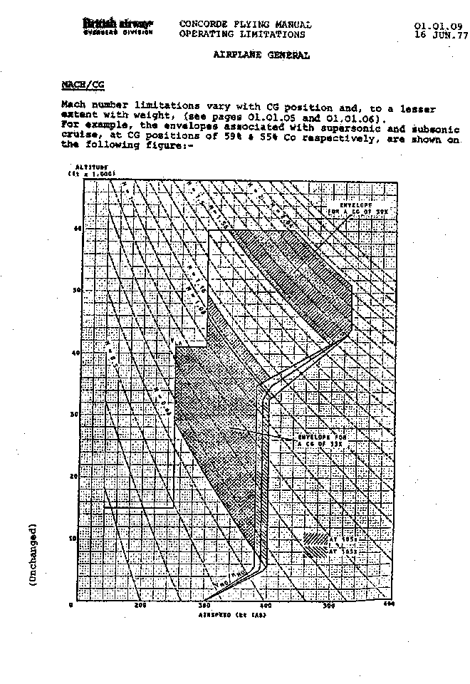
For anybody who wants the full scans to print them out in A4, use these links.
Flight envelope A4 format
light envelope w. CG limits A4 format
Apologies for the mediocre quality of the scans...
CJ
Subjects
C of G
Flight Envelope
Links are to this post in the relevant subject page so that this post can be seen in context.
Reply to this quoting this original post. You need to be logged in. Not available on closed threads.
September 06, 2010, 16:42:00 GMT
permalink Post: 5917627
TAS (true air speed) is simple, it's the true speed of the aircraft through the air.
GS (ground speed) is equally simple, it's the speed of the aircraft over the ground i.e., TAS plus the component of the wind along the flight path. If your TAS is 1300 mph and you have a 100 mph tailwind, your GS will be 1400 mph.
Mach no. is TAS divided by the local speed of sound.
The speed of sound in air depends almost exclusively on the temperature: in a ' standard ' atmosphere it's 760 mph on the ground at +15\xb0C, drops to 660 mph at 37000ft / -57\xb0C and remains constant above that height.
It's IAS (indicated air speed) that's complicated....
Lift, drag, control forces, stability, etc. are all proportional to the 'dynamic pressure' that the aircraft experiences moving through the air.
This 'dynamic pressure' is proportional to density x TAS squared .
Now take an aircraft flying along horizontally at sea level, say at 200 mph.
Lift = weight, so the aircraft stays on a horizontal flight path.
Take this same plane, without changing anything else, to an altitude where the air density is half that at sea level.
Dynamic pressure is now half, so the lift is half as well, but the weight is still the same, so the aircraft can no longer fly horizontally.
So what do we do... we increase the TAS until the dynamic pressure is the same as it was at 200 mph at sea level.
Half the density, so (TAS squared) has to be double, so TAS has to be increased to 1.4 (sqrt of 2) x 200 mph = 280 mph.
This is somewhat confusing for the pilot.... He flies the same aircraft, same weight, same angle of attack, etc. but not the same TAS... he'd have to mentally juggle airspeed and density (altitude) the whole time to maintain horizontal flight at different levels.
It would be much easier if he had an indicator showing dynamic pressure... and maintain that constant for different altitudes.
This is where IAS comes in.
Stick your hand out of a car window. The force you feel is due to the dynamic pressure.
Stick a tube, closed at one end, into the airstream and measure the pressure with a basic pressure indicator, that's your dynamic pressure.
Now the 'clever' bit. Mark your indicator, not in bar or psi, but in mph, so that at sea level it will indicate the same speed as the TAS (200 mph in the example).
Now, same as above, go and fly at an altitude where the density is half, with a TAS of 280 mph. Your indicator will still show 200 mph, showing you that the dynamic pressure, hence the forces (lift, drag, etc.) are the same as those at sea level at 200 mph.
So the 200 mph is your IAS, your "indicated air speed".
It's the IAS that tells you what happens to your aircraft in terms of the forces and aerodynamics, and that's why figures such as the Vne (never-exceed speed) or the stall speed are always in mph or knots IAS , not TAS.
As a matter of fact, a pilot is not very much interested in TAS as such, and most aircraft do not even have a TAS indicator.
It's not until you start approaching the speed of sound that TAS becomes important, and even then it's not TAS as such that's used but its relation to the speed of sound, i.e., the Mach number.
OK, Shanewhite , it's a long and complicated description, but maybe it helps?
CJ
Edit PS : I see mykul10 already had a go as well. So much the better, explanations from two different sides nearly always complement each other!
Subjects
IAS (Indicated Air Speed)
Lift Drag Ratio
TAS (True Air Speed)
Links are to this post in the relevant subject page so that this post can be seen in context.
Reply to this quoting this original post. You need to be logged in. Not available on closed threads.
September 06, 2010, 17:26:00 GMT
permalink Post: 5917714
No... for the manual they've just hatched the limits for a couple of example CGs inside the existing overall limits.
It's the M=1.56 limit that's related to CG, the Mmo=2.04 boundary is purely certification-related.
I think the CG "corridor" is already posted, if not I'll do so.
It's more the other way around... the aft CG limit is 59% for anything above about Mach 1.5.
CJ
Subjects
C of G
Links are to this post in the relevant subject page so that this post can be seen in context.
Reply to this quoting this original post. You need to be logged in. Not available on closed threads.
September 06, 2010, 18:14:00 GMT
permalink Post: 5917809
On Bellerophon's picture, it looks as if the FWD bug on the Mach meter is still at about M=2.2.... and just the barber pole at about M=2.04 as you would expect.
At that exact point in the picture I think he just hit his head against the ceiling... (FL600) but could still stay there a bit more.
Doesn't change any of your other comments, though.
CJ
Subjects
Barber Pole
FL600
Links are to this post in the relevant subject page so that this post can be seen in context.
Reply to this quoting this original post. You need to be logged in. Not available on closed threads.
September 06, 2010, 23:08:00 GMT
permalink Post: 5918422
G-BOAE at Mach 2
Ah, oh, ooooops!!!! Of course it's there, in the little window on the top right of the HSI (Horizontal Situation Indicator, the lower one of the two big central instruments).
Shanewhite , in a way, that illustrates that for flying the aircraft things like TAS and GS are not really that important... that's why there are no big instruments indicating TAS or GS, but only IAS and Mach, with only a little digital window for GS, which IS important for navigation (largely handled by the inertial navigation system, which is the system where the GS display comes from), but not for the minute-to-minute handling of the aircraft.
Bellerophon , dumb question from a techie... the 373 miles is presumably just the distance to the next INS waypoint?
CJ
Subjects
FL600
G-BOAE
IAS (Indicated Air Speed)
INS (Inertial Navigation System)
TAS (True Air Speed)
Links are to this post in the relevant subject page so that this post can be seen in context.
Reply to this quoting this original post. You need to be logged in. Not available on closed threads.
September 07, 2010, 13:27:00 GMT
permalink Post: 5919535
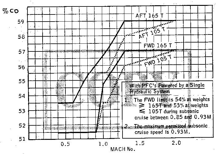
The production a/c diagram is slightly different, but it shows the same kind of "corridor".
Edit : here is the production a/c diagram.
Sorry for the distortion during the scan....
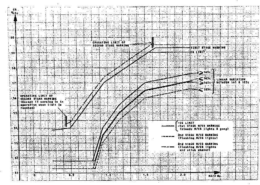
For the full A4 page, use this link :
Prod CG enevlope A4 format
CJ
Last edited by ChristiaanJ; 7th September 2010 at 15:16 .
Subjects
C of G
Links are to this post in the relevant subject page so that this post can be seen in context.
Reply to this quoting this original post. You need to be logged in. Not available on closed threads.
September 07, 2010, 15:34:00 GMT
permalink Post: 5919785
On the two prototypes, the AFCS controller was located on the centre pedestal, and had two big rotary multiposition switches to select the autopilot/flight director modes, plus the autopilot, flight director and autothrottle engage switches.
On the preproduction and production aircraft, the design was totally changed and became the big box with rows of pushbuttons and little handwheels, to set things like altitude and speed, that one now sees at the top centre of the instrument panel, just under the windscreen and above the engine instruments.
It was not until years and years later that I had an occasion to visit a VC-10 cockpit .... to discover how similar the VC-10 AFCS controller was to the prototype Concorde one.
No wonder... both were made by Elliott.
CJ
Subjects
AFCS (Automtic Flight Control System)
Auto-pilot
Auto-throttle
Links are to this post in the relevant subject page so that this post can be seen in context.
Reply to this quoting this original post. You need to be logged in. Not available on closed threads.
September 08, 2010, 11:27:00 GMT
permalink Post: 5921463
So far this thread has been about facts , and stories and anecdotes about Concorde.
While the accident is certainly a subject worth discussing, I've seen enough forum threads on the subject to know they invariably end up with many opinions, but very few facts.
So may I respectfully suggest that, rather than diluting this thread, you open a new one ?
CJ
Subjects
Air France 4590
Links are to this post in the relevant subject page so that this post can be seen in context.
Reply to this quoting this original post. You need to be logged in. Not available on closed threads.
September 08, 2010, 14:04:00 GMT
permalink Post: 5921836
Only the first three Concordes (001, 002 and 01) had a real tail skid (coated with hardwood, IIRC, to prvent sparks).
From aircraft 02 onwards, the skid was replaced by two small wheels, that look as if they've come off a Spitfire....
To understand why it's there, look at a drawing of a side view of Concorde.
If a Concorde overrotates at take-off, or lands with the nose too high, the first things that would have touched the ground are the exhaust nozzles / thrust reverser buckets. The tail skid/wheels are there to prevent that.
As to the need for it...
"Tailstrikes" were rare, but they did happen.
Now I don't remember offhand whether it was already mentioned here or somewhere else, but more often than not those tail wheels were not much good, and got shoved back into the tail, with the reverser buckets still hitting the ground : there are photos of repairs to the buckets to prove it !
CJ
Subjects
Nozzles
Tail Skid
Thrust Reversers
Links are to this post in the relevant subject page so that this post can be seen in context.
Reply to this quoting this original post. You need to be logged in. Not available on closed threads.
September 08, 2010, 20:52:00 GMT
permalink Post: 5922726
I think M2dude has already answered your question.
Anyway, herewith a few very crude scribbles to further illustrate your question and his answers.
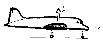
Simplistically, an "old-fashioned" airplane has an asymmetric wing profile (at take-off even more so because of the flaps). Such a profile will start producing lift as soon as you start moving, and if you had enough take-off space, the aircraft would fly off the ground even without rotating it - in practice you rotate to get a more optimum angle of attack, more lift and a better climb speed to "get over the fence".
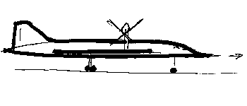
The Concorde wing, in the same circumstances, is little better than a big flat plank, and will not produce any lift at all, or at least far too little to carry the aircraft.
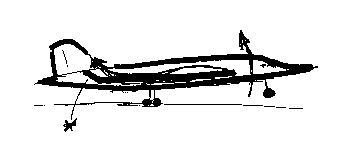
As M2dude already said, raising the elevons produces enough of a downforce at the trailing edge to lift the nose, and from there on the wing does start producing lift.
Not quite conventional lift, but "vortex lift" (a different subject), but lift just the same.
CJ
Last edited by ChristiaanJ; 8th September 2010 at 21:42 . Reason: Resizing a picture, typos
Subjects
Elevons
Vortex
Links are to this post in the relevant subject page so that this post can be seen in context.
Reply to this quoting this original post. You need to be logged in. Not available on closed threads.
September 08, 2010, 22:53:00 GMT
permalink Post: 5922984
Concorde Paris crash, questions, facts, opinions
Can we post any specific questions and discussions on that specific subject over there, please ???
CJ
Subjects
Air France 4590
Links are to this post in the relevant subject page so that this post can be seen in context.
Reply to this quoting this original post. You need to be logged in. Not available on closed threads.