December 22, 2010, 15:40:00 GMT
permalink Post: 6137696
CliveL
Last edited by CliveL; 22nd December 2010 at 16:23 . Reason: add a picture
Subjects: None
No recorded likes for this post (could be before pprune supported 'likes').Reply to this quoting this original post. You need to be logged in. Not available on closed threads.
December 22, 2010, 20:13:00 GMT
permalink Post: 6138211
Ultimately applied a further nose down elevon input (4 degrees????) if EAS was less than (140kts???? That's a VERY low speed). (Colloquially known as 'super-duper stab' on my course)
To cover this case the 'superautostabiliser'was developed. It effectively restricts the rate of variation of incidence so that, if the pilot entered into an avoidance manoeuvre of sufficient magnitude to trigger the stick wobbler, i.e. about 1.5g, he would be able to recover easily without exceeding the maximum incidence demonstrated in flight (which was in fact slightly greater than the maximum steady incidence limit). This superautostab had gain scheduled against AoA and also included phase advanced pitch rate and speed terms. Finally, there was a 'yaw superautostabiliser which applied rudder as a function of lateral acceleration to restrict sideslip which (see below) could affect the maximum lift attainable. [Note that because of the dynamics of slender aircraft operating at high AoA it was readily possible to develop sideslip in a turn]
Hope that is clear.
Whilst talking about maximum lift etc. can I confirm the numbers quoted in an earlier posting for the start of vortex lift - about 6 or 7 deg AoA at low speed, and for the AoA at maximum lift - about 23 deg. This is where the pitching momemt curve vs AoA 'breaks'. It is not a stall in the conventional sense because of course the flow over the leading edge has been separated long ago. Instead it is the AoA at which the LE vortices become 'too big for their boots' and go unstable and 'burst'. This AoA is sensitive to sideslip and the leading wing half will go first.
CliveL
Subjects
AFCS (Automtic Flight Control System)
AoA
Auto-trim
Elevons
Mach Trim
Rudder
Sideslip
Trim
Vortex
Links are to this post in the relevant subject page so that this post can be seen in context.
Reply to this quoting this original post. You need to be logged in. Not available on closed threads.
December 22, 2010, 21:30:00 GMT
permalink Post: 6138333
CliveL
Subjects
AICU (Air Intake Control Computer)
Links are to this post in the relevant subject page so that this post can be seen in context.
Reply to this quoting this original post. You need to be logged in. Not available on closed threads.
December 23, 2010, 15:16:00 GMT
permalink Post: 6139610
I had never heard of any such stiffeners before I started reading this thread.
The wing inboard of Rib 12 was pretty stiff as was Rib 12 itself, so it didn't need stiffening there.
I don't see how tiny stiffeners like that, mounted INBOARD of Rib 12 could ever have have any significant stiffening effect on the wing OUTBOARD of Rib 12. if anyone wanted to stiffen the outer wing it would be much more efficient to do it with internal structure, so any external addition would have been some sort of panic measure and I think I would have heard of it.
The external shape of the excrescence looks to me much more like a streamlined fairing to get some sort of cable or pipe from A to B when for some reason it couldn't be passed through inside the wing. In this connection I see that the objects in question run fairly close if not along, area where one might have something going from tank 5a to 6 or 7 to 7a.
Yes there would be a small performance penalty for these fairings.
In summary I don't really know, but would need a lot of convincing that these things really were external stiffeners!
CliveL
Subjects
Fairford
Filton
Links are to this post in the relevant subject page so that this post can be seen in context.
Reply to this quoting this original post. You need to be logged in. Not available on closed threads.
December 23, 2010, 17:12:00 GMT
permalink Post: 6139823
Any chance of a pic or a drawing, M2dude?
It seems almost impossible to me that it was 'something' between inner and outer wing, since it would have had to 'jump' over the bathtub covers.
IMO everything went through rib 12, not under or over it.
'Bathtub covers' rings a bell - we did have an issue designing fairingsfor these that looked remarkably like those in the photographs I've been looking at, but I'm damned if I can remember what the bathtubs were! (getting old again) Aren't those so called stiffeners actually the bathtub covers? Or have I completely misunderstood the question?
CliveL
Subjects: None
No recorded likes for this post (could be before pprune supported 'likes').Reply to this quoting this original post. You need to be logged in. Not available on closed threads.
December 23, 2010, 17:21:00 GMT
permalink Post: 6139847

Dude, Do you know how the #2 system was exhausted if it wasn't through another thrust recovery nozzle? We were never going to throw away 600 lbf thrust every other flight - not on Concorde where we sweated blood to get the parasitic drag down!
Any chance that there was a common discharge point even if the two packs were used alternately?
CliveL
Subjects
Nozzles
Links are to this post in the relevant subject page so that this post can be seen in context.
Reply to this quoting this original post. You need to be logged in. Not available on closed threads.
December 23, 2010, 18:08:00 GMT
permalink Post: 6139927
No perf penalty, as 'Dude noted. I vaguely recall being told that the drag from the recuperator cancelled a lot of the recovered thrust. I've no idea how true it was.........
I know it sounds crazy, but that cabin air had to be dumped somewhere, and without those thrust recovery nozzles all the energy it contained would be lost, so that a net zero is actually a win!
CliveL
Subjects
Nozzles
Links are to this post in the relevant subject page so that this post can be seen in context.
Reply to this quoting this original post. You need to be logged in. Not available on closed threads.
December 23, 2010, 19:43:00 GMT
permalink Post: 6140089
CliveL
Subjects: None
No recorded likes for this post (could be before pprune supported 'likes').Reply to this quoting this original post. You need to be logged in. Not available on closed threads.
December 23, 2010, 20:01:00 GMT
permalink Post: 6140122
These strengthening straps were fitted a few years after the start of service due to small cracks appearing in the outer wing, and only seen on BA aircraft. This was put down to the fact that in the early years BA Concordes flew heavy and subsonic for extended periods across Europe, on their route to Bahrain, whereas Air France aircraft always accelerated shortly after take off
Also either side of the engines there were two tubes on the underwing which went fore /aft. These tubes were the drain outlet for their respective engine dry bay and directed any fluid to the trailing edge of the wing.
If there were spanwise straps fitted to BA aircraft after a few years in service that was after my time. They would be a sort of 'crack stopper' and despite the drag would have to go spanwise to carry the loads and would have to be external at that stage in the aircraft life. They would give some additional bending stiffness, but not very much I think. they are probably invisible in any photographs I have - the 'fairings' I have been chuntering on about are the dry bay drains you have just described.
I must admit I am surprised by your remarks on the thrust recovery nozzles though.
CliveL
Subjects
British Airways
Nozzles
Links are to this post in the relevant subject page so that this post can be seen in context.
Reply to this quoting this original post. You need to be logged in. Not available on closed threads.
December 24, 2010, 11:55:00 GMT
permalink Post: 6141200
Happy Christmas to all
CliveL
Subjects
Elevons
Links are to this post in the relevant subject page so that this post can be seen in context.
Reply to this quoting this original post. You need to be logged in. Not available on closed threads.
December 24, 2010, 12:21:00 GMT
permalink Post: 6141242
CliveL
On the other hand, if we ignore Dude's instruction to go inboard and aft, then there could be spanwise straps ahead of/behind the 'F' of the registration out past the hyphen. Best leave it to those who know I think!
Last edited by CliveL; 24th December 2010 at 12:28 . Reason: wrong name
Subjects
Air France
British Airways
Links are to this post in the relevant subject page so that this post can be seen in context.
Reply to this quoting this original post. You need to be logged in. Not available on closed threads.
December 24, 2010, 13:02:00 GMT
permalink Post: 6141291
 Christian asked if there was an aerodynamicist in the house - I guess that would be me!
The original question was whether there was any vortex activity in subsonic cruise, but the discussion went on to ask about designing for subsonic drag I think.
The answer to the first bit is that the vortex flow started in a gentle manner from about 6 or 7 deg AoA and got steadily stronger. Depending on the chosen cruise speed and the aircraft weight, the subsonic cruise AoA would have been in the region of 4.5 to 5 degrees, i.e. below any significant vortex development. 6/7 deg would correspond to something in the range 250 to 280 kts probably (I haven't done the sums)
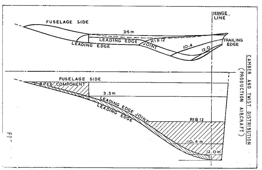
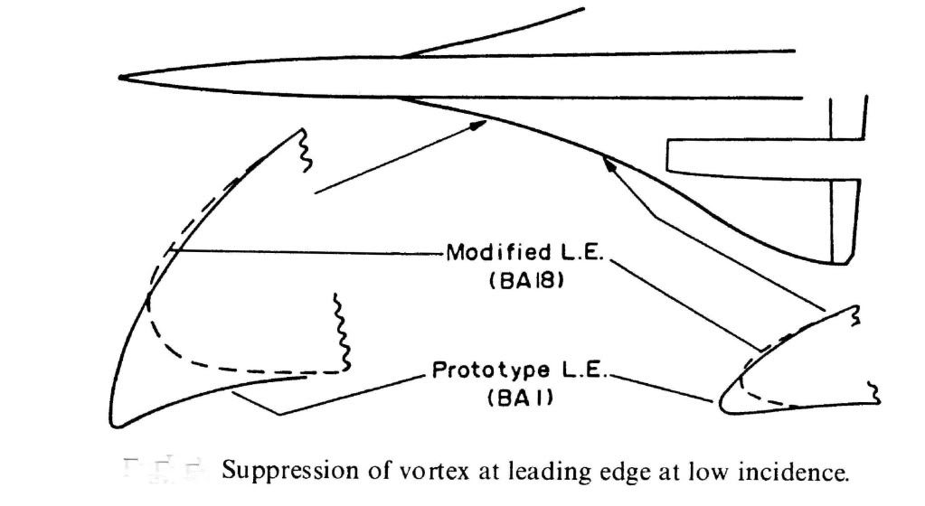
What we were trying to do for subsonic cruise was to have what is known in the trade as 'leading edge suction' acting on a nice bit of forward facing area so that it tried to drag the aircraft forwards as it were. As you can see from the diagram the prototype aircraft had a much more cambered LE so that both suction and forward facing area were very reasonable. This prototype shape was nicely rounded so that LE separation and top surface vortex generation started at a higher AoA than on the production aircraft. Unfortunately this shape, which featured a rather sharp LE on the undersurface, generated a vortex on the undersurface of the wing in supersonic flight and low AoA (near zero 'g'). This vortex got into the intake and caused the engine to surge, so we had to redesign the LE ahead of the intakes as shown. This cost us a little subsonic drag, so you can see from the diagram what you need to do to keep subsonic cruise drag down.
Hope this answers the questions
CliveL
Subjects
AoA
Engine surge
Intakes
Vortex
Links are to this post in the relevant subject page so that this post can be seen in context.
Reply to this quoting this original post. You need to be logged in. Not available on closed threads.
December 24, 2010, 17:56:00 GMT
permalink Post: 6141738
Hell Mike, I meant I should leave it for others who definitely know, not you!
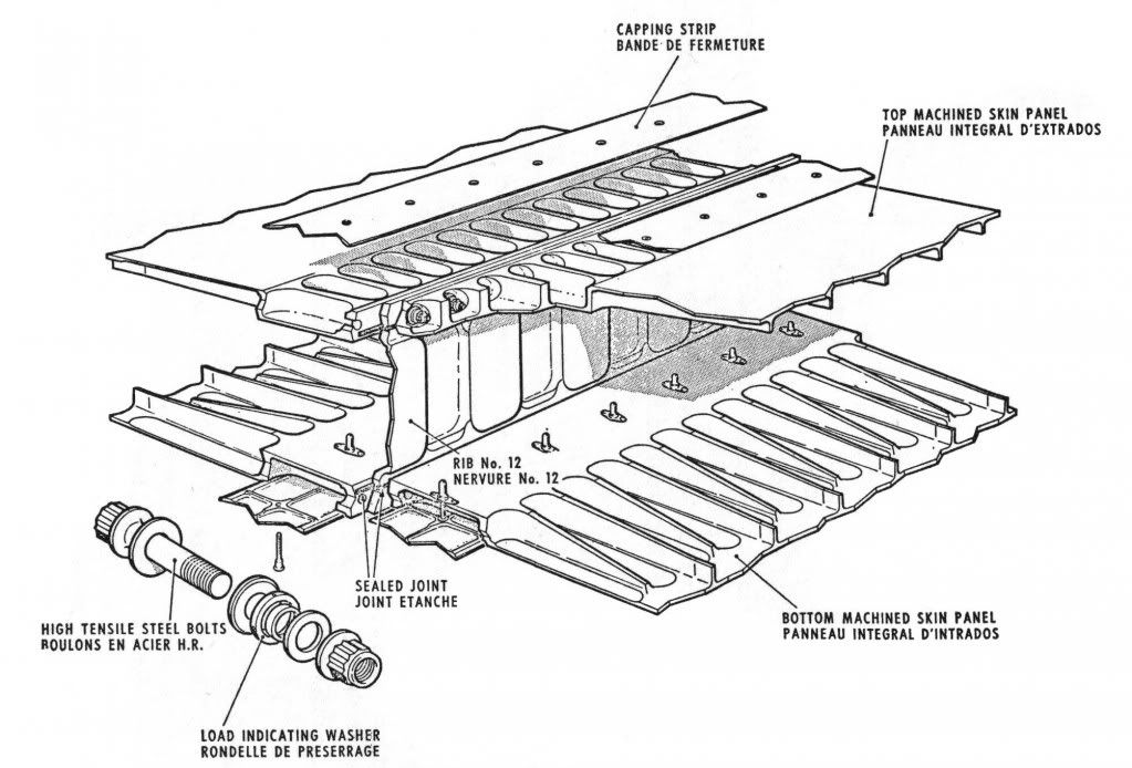
[xxxxquote]A little p.s. from me - having looked at Clive's diagram on this page showing the bathtubs, aren't the strengtheners the oval cups outboard of the main fixings on the page? with one pointed to by the words "Bottom machined skin panel"?
This looks like it's another layer of shear in order to fulfil the brief of working around the reported skin problems in that area. Just strange it had to break the surface like that? [xxxx/quote]
I don't think so Mike, there are far too many of them. It looks more like 'pocketing' of the machined skin to reduce weight; and incidentally that SA overdid it, since there were clearly cracks developing along the spanwise joints between the various wing sections.
Incidentally, doesn't that picture show ever so clearly why designing and fitting that postGonesse Kevlar liner to the lower skins was such a difficult job!
[xxxxquote=ChristiaanJ]If so, they are indeed shown in the structural repair manual and listed as 'doublers'. There are ten of those, from spar 62 to spar 71.
Reading "between the lines", the modification dates from about 1978, and was applied by successive service bulletins to both the BA and AF aircraft. [xxxx/quote]
Yes, I agree, they look like skin doublers put on as a repair job, and that makes (to me) a lot more sense than additions to increase outer wing stiffness. What has confused me from the beginning was that I equated "outer wing stiffness" with "outer wing torsional stiffness" because I could see why somebody might want to increase that but I couldn't, and can't, see why anyone would want to increase outer wing bending stiffness - if you get a little more dihedral who cares? But additional material to increase or recover fatigue life is another matter altogether.
Why external? Just look at that drawing - where could you add additional bending material easily?
[xxxxquote=Landroger]Digital control is a hell of a lot easier than Analogue - in my humble opinion.[xxxx/quote]
Depends when you were born Roger. Now if you came into this world before WW2 ......
[xxxxquote=Mr Vortex]I'm was wondering that, according to the manual and some document said that the vortex lift start to form on wing tip first. Why's that happened? Why not the root of the wing first?
Is it cause by the local wing tip vortex push the air causing more upwash
and hence more effective AoA causing it to reach the stall AoA first is that right?
Also, does the wing vortex on the Concorde has an influence or the effect on
the rudder? [xxxx/quote]
Ah! this gets a little complicated. Every lifting wing generates a pair of vortices at the tip, but these are not the vortices most people associate with Concorde. The massive vortices you see when the air is moist and the water vapour condenses out because of the drop in air pressure inside the vortex start, as you suggest at the wing root from that highly swept leading edge. The wingtip vortices are still there, even when the main vortices are doing their stuff, so Concorde actually has two sets of vortices acting on the upper surface, although this is not obvious to the casual observer.
Simply, the wing vortex has no effect on the rudder.
But whilst I am writing about vortices, can I digress to talk about the 'moustaches' aka GT6. Somebody, I forget who, asked about their use for controlling longitudinal stability and somebody else replied, quite correctly, that they were a contribution to lateral stability. What was happening without them was that high AoA (by which I mean in excess of about 10~12 degrees) the 'crossflow' on the front fuselage generated a pair of small vortices which, in sideslip, wandered across the base of the fin. This gave some sidewash that cancelled the 'incidence' coming from the sideslip itself so that the bottom of the fin was effectively operating at zero slip and therefore zero lift. Result - the weathercock stability dropped to virtually zero for small sideslip angles. The small vortex generators (Generator Turbillon or GT) had the effect of fixing the location of the origin of the forebody vortices so that they didn't wander - in fact they tended to become entrained into the main wing vortices - problem solved.
Now if I can sort it out I will try to upload some pretty pictures showing those two sets of wing vortices.
CliveL
Subjects
Air France
AoA
British Airways
Fatigue
Rudder
Sideslip
Vortex
Links are to this post in the relevant subject page so that this post can be seen in context.
Reply to this quoting this original post. You need to be logged in. Not available on closed threads.
December 24, 2010, 18:25:00 GMT
permalink Post: 6141781
 ">
">
Dammit! I thought I had read that [xxxxquote] gave me one of those pretty text boxes ah well, back to the drawing board.....
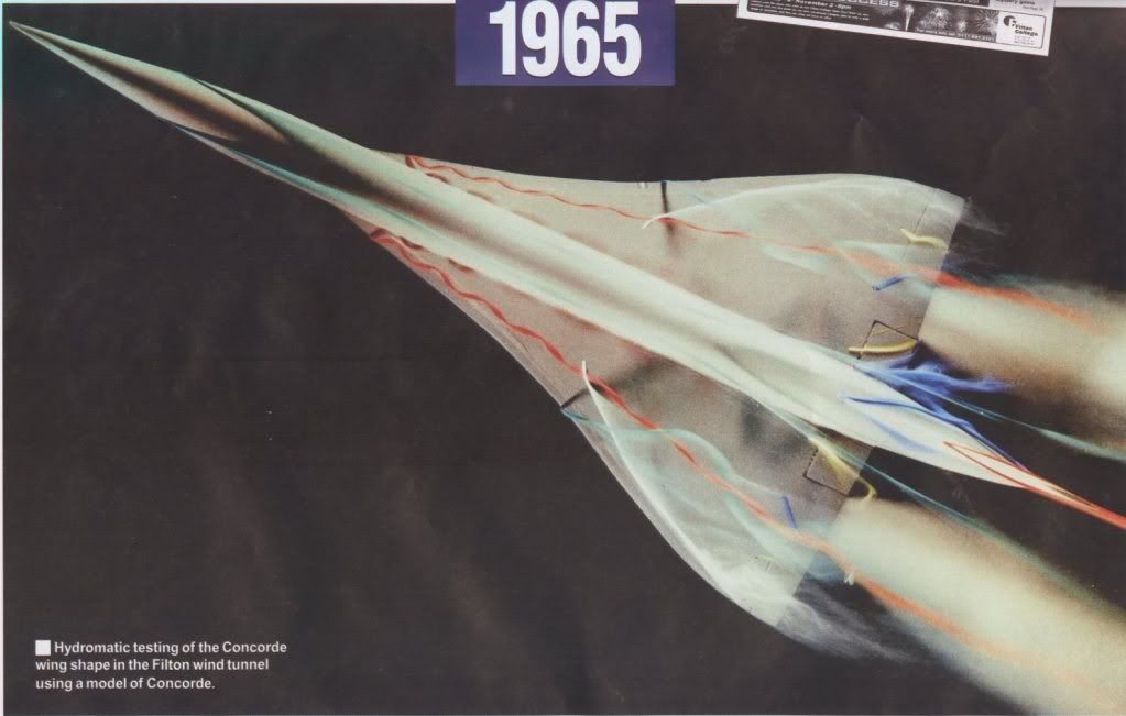
Unfortunately the only flow visualisation pictures I have are taken at AoAs where the tip vortex has been swallowed by the main vortex, but I thought I would paste them anyway as most people would never have seen them. In this one you can see the forebody vortices quite clearly (the bluegreen streaks) but since it is a zero sideslip case they don't go anywhere near the fin.
On closer inspection, maybe you can just see the wingtip vortices as separate bits of curly white smoke very close to each wingtip.
I'm not going to risk losing all that typing trying to attach a second picture, so I will send that separately
CliveL
Subjects
Sideslip
Vortex
Links are to this post in the relevant subject page so that this post can be seen in context.
Reply to this quoting this original post. You need to be logged in. Not available on closed threads.
December 24, 2010, 18:28:00 GMT
permalink Post: 6141784
OK, here is another one .....
CliveL
Subjects: None
No recorded likes for this post (could be before pprune supported 'likes').Reply to this quoting this original post. You need to be logged in. Not available on closed threads.
December 26, 2010, 08:21:00 GMT
permalink Post: 6143472
Generally speaking the region from say 0.98 to 1.2M is one to pass through and be thankful!
CliveL
Subjects
C of G
FL600
Links are to this post in the relevant subject page so that this post can be seen in context.
Reply to this quoting this original post. You need to be logged in. Not available on closed threads.
December 26, 2010, 09:38:00 GMT
permalink Post: 6143531
Lets start with a comparison of the lft on a conventional subsonic wing with that of a slender wing like Concorde:
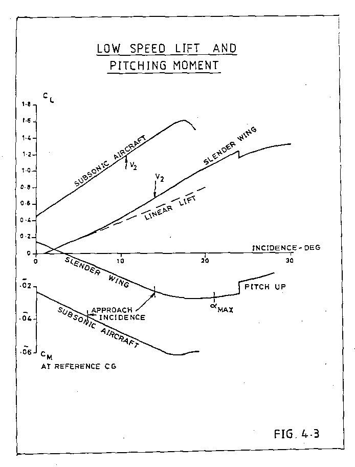
The subsonic line is linear, the slope depends on the geometry of the wing; high aspect ratio wings have a higher slope than low aspect ratio, unswept wings a higher slope than swept. Concorde, being a low aspect ratio swept wing has no chance!
To get a decent approach speed with a delta wing which has 'conventional' wing sections you need either a long U/C and work with high landing AoA or a large wing area to get the wing loading down. I would put the Avro Vulcan in the latter class. A large wing area is bad news for supersonic aircraft, but the Germans, working during WW2 found that if you give the delta sharp leading edges the flow separates at the leading edge and forms a pair of vortices that flow over the upper wing surface.
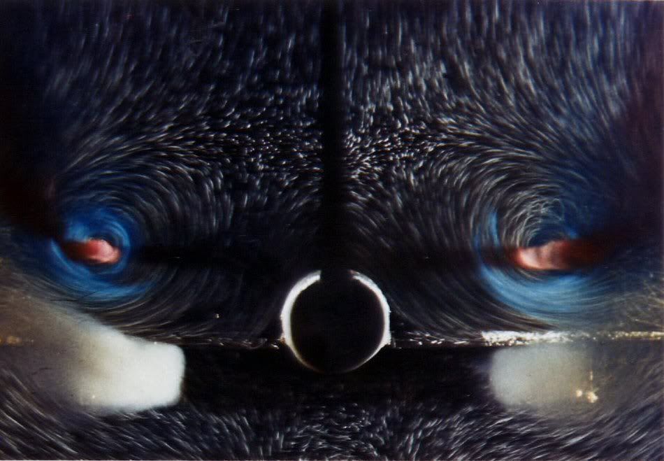
A vortex, if you could see it, is like a tornado (twister) turned on its side. The essential feature is that it is associated with low static pressures. As you get closer to the centre of the vortex the pressure drops more and more. The red zones at the centre of that transverse view are very low pressure indeed, but even the outer zones have quite low pressure.
I will have to put it up as a separate posting, but there are pictures that show that as AoA increases not only does the vortex get stronger (more suction) but the area of the wing affected by the vortex also inceases. This 'double whammy' gives the vortex a nonlinear effect. This 'nonlinear' lift is what is sometimes called 'vortex lift'.
It doesn't come for nothing - since by definition the flow is separated from the leading edge there is no alleviating 'leading edge suction' to reduce drag, and you won't go very far wrong if you take the drag of an aircraft with such a wing as Profile Drag plus Lift (times) tan AoA.
Concorde is a bit more subtle - the nose of the wing is drooped so that the flow does not separate until the AoA reaches 6 or 7 deg, giving us a good L/D in subsonic cruise whilst still having a healthy lift at approach speed.
Does this fit the bill?
CliveL
Subjects
AoA
Vortex
Links are to this post in the relevant subject page so that this post can be seen in context.
Reply to this quoting this original post. You need to be logged in. Not available on closed threads.
December 26, 2010, 09:51:00 GMT
permalink Post: 6143540
 Ok, second picture (can anyone tell me how to attach more than one?)
These need a bit of explaining I'm afraid. They are 'oil flow' pictures - you paint the model wing with a mixture of paraffin, engine oil and lamp black and blow air over it. The resulting pattern shows how the air is flowing (or not flowing, which is its primary purpose) over the wing surface.
I the diagram marked up in red the 'S' shaped line is a typical streamline where the air is brought down onto the surface inboard, moves downstream and across towards the tip under the combined action of fore and aft velocity and vortex rotational velocity and tis finally lifted off the surface by the vortex. the triangular zone marked out in red is the area of the wing 'scrubbed' by the vortex flow. If you compare the pictures at various AoA you will see that this area increases substantially as AoA increases.
On the21 deg picture you can also see signs of a second vortex between the main vortex and the wingtip, but this is not the classic 'tip vortex'
CliveL
Subjects
AoA
Vortex
Links are to this post in the relevant subject page so that this post can be seen in context.
Reply to this quoting this original post. You need to be logged in. Not available on closed threads.
December 26, 2010, 15:25:00 GMT
permalink Post: 6143923
CliveL
Subjects
V2
Links are to this post in the relevant subject page so that this post can be seen in context.
Reply to this quoting this original post. You need to be logged in. Not available on closed threads.
December 26, 2010, 18:47:00 GMT
permalink Post: 6144161
One would expect a curve for constant alpha max against IAS and altitude, not the staircase in the diagram.
Was this for simplicity of use of the diagram?[quote]
I don't have a complete explanation for all the regions - it was a long time ago and I'll need to dig, but:
Below 16000 ft Vla obviously needs to go as low as Vref to cover landing at elevated airfield altitudes. At present I don't have a satisfactory explanation for 250 kts between 16000 ft and about 45000 ft (250kts/Mach 1.0) A constant value in IAS is what you would get for a constant CLmax (the alphamax is not really the driver). Vla should give a margin above stall, and a quick sum suggests that 250 kts would be consistent with a 1.3Vs condition and a CLmax of about 0.8 up to Mach 1.0, which is not unreasonable, but I am not saying that is the correct interpretation.
From 45000 ft to 60,000 ft I think Vla may be set by manoeuvre requirements. Certainly the forward CG envelope boundary between 1.0M and 1.5M discussed in earlier posts is very close to the requirement to be able to pull 1.2g with half hinge moment available at Vla and heavy weights. Again not certain, but best guess at the moment.
This is the 'simplest' one: it was the highest 'safe' altitude from which an emergency descent could be made, in the case of a window blowing out, without having the blood of the pax boil....
Test flights (without pax, and with the crew pressure-breathing oxygen) did go as high as 69,000ft.
[quote ]Mmo (max operating Mach number)
Mach 2.04 is usually quoted as having been chosen to assure an adequate life of the airframe.
But what effect does a higher Mach number as such have?
Or are Mmo and Tmo (127\xb0C) directly related?[quote]
I have always been puzzled by this statement as one does not normally associate Mach Number with a life limit. Going through my collection of lectures I found another, more plausible explanation:
quote" The scheduled cruise mach Number was 2.0. associated with a structural total temperature of 400 degK. Above ISA +5 Mc was cut back to maintain 400 degK.
To cope with variations of flight mach Number about Mc associated with often rapid and significant changes in wind and temperature which occur particularly in the vicinity of the tropopause (which can of course be as high as 60,000 ft in the tropics) a maximum operating Mach Number (Mmo) of 2.04 is selected" unquote [Leynaert, Collard and Brown, AGARD Flight Mechanics Symposium October 1983]
This is much more in line with my memory on this subject.
I suppose this is related to structural limits (qmax)?
What is the limiting factor here (other than qmax)?
What is the limiting factor here? The answer will no doubt also explain why this is slightly weight-dependent.
Why the sudden change below 5,000ft?
a) there is absolutely no advantage is having a high Vmo at low altitudes as it could not be exploited even if one wanted to because of ATC limitations to 250 kts below 10,000 ft (in the USA at least)
b) there are a lot of things that get rapidly worse if you encounter them at high speed and which are anyway more likely at low altitude - hail, birds etc.
So why store up trouble for yourself!
CliveL
Subjects
C of G
Depressurisation
IAS (Indicated Air Speed)
Mmo
TMO (Temprature Max Operating)
Vmo
Vref
Links are to this post in the relevant subject page so that this post can be seen in context.
Reply to this quoting this original post. You need to be logged in. Not available on closed threads.