CliveL January 18, 2011, 16:56:00 GMT permalink
Post: 6187329
Originally Posted by
M2Dude
I confess. I'm afraid that I did intentially use that awful pun (sorry
).
Shame on you
Yes, the 188 was welded stainless and as you said, manufacturing was a pain. I didn't work on that aircraft myself, but one reported episode in the flight test programme is worth a digression off topic. Dialogue (maybe that should be monologue) between aircraft and FT control:
t = 0
Godfrey Auty (test pilot): "Mach ... port engine flamed out"
Silence from ground
t = 10secs
G.A.: "Mach .... starboard engine flamed out"
Silence from ground
t= 15 secs
G.A. "Well for Chrissake say something, even if it's only goodbye!"
Luckily the restart drills worked
After those AICU problems the boss came to see me (I was running the S&C section at the time) and said "Your blokes are doing dynamic simulation of aircraft response (on ANALOGUE computers!), do you think they could simulate the 188 intake control system?". To which of course there is only one answer possible, but that is how the two aerodynamicists who did most of the pioneering work on the Concorde AICU came to work together - Derek Morriss from the 188 project and Terry Brown from the S&C group. And boy were we lucky to have that combination
For the record, if my memory serves, the simulation showed that the 188 problem was hysteresis in the mechanical part of the 188 AICU.
CliveL January 19, 2011, 08:27:00 GMT permalink
Post: 6188447
Here is the one of the 'forward' pages from 'The Concorde Air Intake Control System' publication: (Issue 3 Feb' 2001). There just might be a name or two there that rings a bell.
Yes there are a few bells ringing, although one or two names are phonetically spelt
Etienne would appreciate being called 'Wise' rather than Fage I'm sure!
Never before heard of that publication - how can I get to read copies?
Best regards
CliveL
SubjectsIntakes
Links are to this post in the relevant subject page so that this post can be seen in context.
No recorded likes for this post (could be before pprune supported 'likes').
CliveL January 30, 2011, 07:35:00 GMT permalink
Post: 6212066
When passing Mach 1, the nose shock wave moves rearwards, and passes over the static ports.
As a result, there is a "twitch" on both the altimeter (barely visible) and on the VSI (verical speed indicator, very visible) when exceeding Mach 1.
To further complement the answer, Concorde's static ports are mounted on much bigger plates than usually seen. This is because in supersonic flight the static pressure is peculiarly sensitive to the actual angle of the skin around the 'hole' relative to freestream. Consequently the ports are set in plates that have been machined flat. These plates were then jig-set to accurate angles relative to body datum.
CL
SubjectsStatic Ports
Links are to this post in the relevant subject page so that this post can be seen in context.
No recorded likes for this post (could be before pprune supported 'likes').
CliveL January 30, 2011, 19:07:00 GMT permalink
Post: 6213080
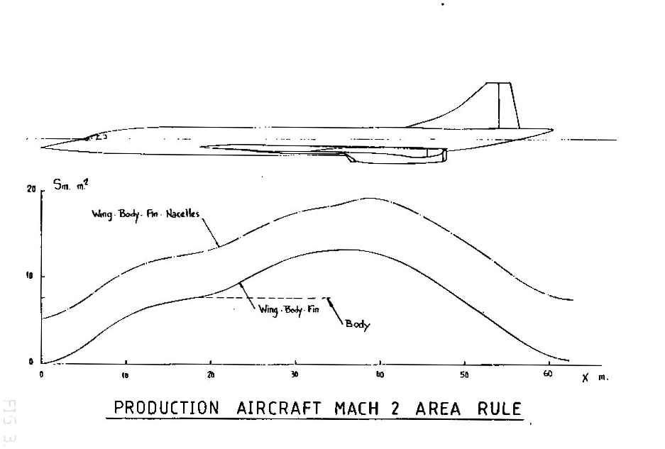
Also just about visible in that picture is the 'area ruling' of the rear fuselage where the fin starts - the fuselage is noticeably 'waisted' there.
Sorry SSD, but there ain't no waisting on the fuselage, although the area ruling in that area is quite good. Did you mean where the fuselage starts to taper?
Dude - I DID say the pressure was peculiarly sensitive to angle, but I didn't remember those additional corrections. Amazing what memories this thread throws up
SubjectsArea Rule
Links are to this post in the relevant subject page so that this post can be seen in context.
No recorded likes for this post (could be before pprune supported 'likes').
CliveL January 31, 2011, 13:50:00 GMT permalink
Post: 6214565
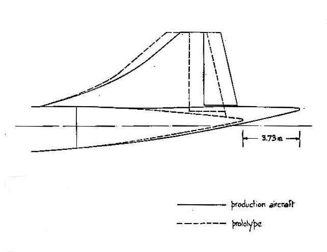
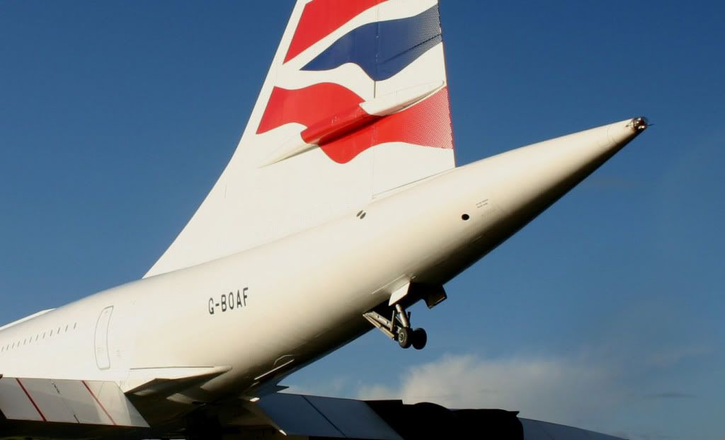
Nope. I meant the waisting of the fuselage where the fin starts. Stand on the steps by the front door where Dude's wife took that picture, and you'll see that the cabin roof is 'waisted in' noticably where the fin is mounted (not the sides of the fuselage which remain parallel - the roof, which is bowed inwards and downwards to reduce the fuselage cross section co-incident with the fin's extension above the fuselage).
OK, I see where you are coming from. There is a change of line at the top of the fuselage, but this doesn't really constitute 'waisting' in my terms. I think of waisting as a local area increase followed by a reduction to fill in a bump in the area distribution. What you are seeing is the change in upper fuselage line where the extended rear fuselage fairs into the prototype fuselage line. This extension was introduced to stretch out the lifting length, but to keep enough ground clearance it had to be upswept, which gave rise to that upper surface kink.
This one really shows it up Alpha Fox after last landing at Filton.
">
Cheers
CL
Last edited by CliveL; 1st February 2011 at
08:58
.
Reason: addition of picture
SubjectsFilton
Links are to this post in the relevant subject page so that this post can be seen in context.
No recorded likes for this post (could be before pprune supported 'likes').
Dude, those are very nice illustrations, but I would make a small correction to the lower picture - the bleed flow is shown as entering the void at the front of the slot between the front and rear ramps whereas in reality it goes (sorry went :-( ) in at the rear behind the terminal shock. The increase in pressure behind that shock was the 'drive' for bleed flow.
Regards
CliveL
SubjectsBleed Air
Links are to this post in the relevant subject page so that this post can be seen in context.
No recorded likes for this post (could be before pprune supported 'likes').
And what do aerodynamisits know about aerodynamics anyway
Well if you ask two aerodynamicists about a problem you will probably get at least three opinions, so there is at least one in three chance of being right whatever you say
CliveL
Subjects:
None
No recorded likes for this post (could be before pprune supported 'likes').
The first bit of the moveable front ramp was carefully shaped to give a sequence of weak shocks that reduced the Mach Number so gradually that shock losses were minimised. This was close to an isentropic process, hence the name. The geometry was arranged so that as the progressive shocks were generated and the Mach angles and shock angles changed the weak shocks tended to 'focus' on a point just ahead of the lower lip. This then became effectively a single 'shock' at that point. Hence isentropic fan shock.
So the lower lip forms a normal shock and the airflow goes subsonic immediately behind it, the supersonic flow above somehow collide and form a shock between the ramps? I understand how the subsonic and supersonic flow coming together would reduce the average velocity -- I'm still surprised the gap between the forward and rear ramps wouldn't act like a divergent surface and cause the supersonic flow to accelerate rather than come down to subsonic speed.
The shock from the lower lip would, on its own, give subsonic flow across the intake, but the change in flow direction where the flow off the solid ramp started to traverse the gap (where Dude's drawing shows the flow going into the void) produced an expansion 'fan' that accelerated the flow in its vicinity and this gave supersonic flow in the upper half of the duct but there was a shear across the height of the duct there. The total
effective
duct area however was convergent back to about the leading edge of the rear ramp, so the Mach Number reduced continually up to that point. Then the 'terminal shock' brought the flow down to below Mach 1 and from there on the divergent subsonic duct did the usual deceleration job. The whole point of the intake geometry was that the purely aerodynamic boundary between main duct and ramp void was infinitely flexible in shape, which made the design very tolerant of flow disturbances.
SubjectsExpansionIntakes
Links are to this post in the relevant subject page so that this post can be seen in context.
No recorded likes for this post (could be before pprune supported 'likes').
Must have been a highly efficient inlet for a Mach 2 plane: Two traditional oblique waves; a fan-shock (also oblique); a shockwave off the lip that is normal and oblique depending on how far you are away from the lip, and a normal terminal shock.
Yes is was very efficient - 94.7% pressure recovery at M 2.0 cruise
So, isentropic would, in this context, mean that no shock-losses occurred at all?
In theory yes, but in practice there was a small loss.
SubjectsIntakesShockwave
Links are to this post in the relevant subject page so that this post can be seen in context.
No recorded likes for this post (could be before pprune supported 'likes').
Investigations revealed that the vibrations were as the result of vorticies swirling into #4 intake, in an anti-clockwise direction, coming off the R/H wing leading edge.
Only one comment Dude; as I said to you in a PM the vortices came off the intake sidewall leading edge rather than the wing. If you think about it, the highly swept, sharp leading edge of the sidewall looks just like a delta wing on its side, so that flow coming on to the sidewall leading edge from the outside generates a vortex just like that above the main wing, but now going inside the intake. At low speeds the engine is sucking in air from everywhere it can, so there is a substantial flow entering from the side of the intake. As you increase speed the potential air supply coming from the streamtube directly ahead of the intake increases enormously so the 'sidewash' onto the intake sidewall diminishes and the vortex is suppressed. On the other side of the aircraft of course the sidewall vortex was handed the other way.
Last edited by CliveL; 8th April 2011 at
08:18
.
SubjectsIntakesVortex
Links are to this post in the relevant subject page so that this post can be seen in context.
No recorded likes for this post (could be before pprune supported 'likes').
So how was the Concorde's airframe life calculated ?? Flying hours or perhaps pressurisation cycles ? Did a higher altitude effect anything since there would be a higher differential pressure??
I can't answer for the engines, but the airframe life was going to be limited by thermal fatigue cycles. There was an on-going programme of testing at RAE Farnborough where, from memory, 21000 cycles had been accumulated by the time it was shut down. The airworthiness authorities were demanding a safety factor of 3 because nobody had flown under that sort of limit before, so the theoretical life would have been 7000 flights.
Not so bad as it sounds in calendar years, as the annual utilisation of any one aircraft was very low, and there would also have been scope for life extension by applying certain modifications to the fuselage.
Dude, can I join Christiaan in requesting more information on that '5000' series numbering; I have never come across it before.
Also, I have asked the CAA surveyor who was most likely to have made that reskinning decision for more data. Perhaps he can remember the problem with the forward fuselage skins. Certainly when we were standing together inside 102 last week and talking about fuselage modifications for relifing the aircraft the problem of Component 30 was not mentioned!
I'll keep you in touch.
CliveL
PS: You were going to get a lot for your \xa330
Subjects:
None
No recorded likes for this post (could be before pprune supported 'likes').
The production series aircraft had a thicker skin here, and we were told that the CAA insisted on this being done as part of any conversion to airliner standard.
I have now asked two senior CAA surveyors about this, and neither remember anything but the crown modifications that went with RELIFE. Sounds like somebody didn't want to do the conversion
CliveL
SubjectsCrown Modification
Links are to this post in the relevant subject page so that this post can be seen in context.
No recorded likes for this post (could be before pprune supported 'likes').
When not generating vortex lift, was the airflow attached over both the upper and lower wing surface?
As the IAS decreased and AoA increased, the vortex started at the leading edge, and gradually grew in both size and contribution to overall lift until the vortex (or vortices) accounted for all the lifting force.
The simple answer is yes, it was attached flow.
The vortices never provided all the lifting force. Up to about 6 or 7 deg AoA there was no vortex lift, just the usual wing tip vortices. Above that AoA the non-linear (vortex) lift grew steadily until at stall (about 23 deg AoA) the vortex lift was around 45% of the total.
SubjectsAoAIAS (Indicated Air Speed)Vortex
Links are to this post in the relevant subject page so that this post can be seen in context.
No recorded likes for this post (could be before pprune supported 'likes').
Was the vortex lift characteristic of the ogee wing aerodynamics fully understood before the aero configuration of Concorde was finalised?
I would say that it was. Remember that the design went through several phases before it was finalised and we did an awful lot of testing and tweaking of the detailed geometry to eliminate a gradual pitch-up and to increase the vortex lift at any given AoA, so by the time we defined the production aircraft wing we knew pretty well all there was to know about vortex development from the AoA at which it started right through to the AoA at which the vortices burst.
How much did the BAC 221 (the Fairey Delta II analog of Concorde) contribute to the understanding of vortex lift of this wing?
The BAC221 didn't contribute much to the details of this understanding as it was rather too late to help in prototype definition and the production development was all about the details of planform, camber and twist. But then the 221 wasn't intended to study vortex development; it was built to examine the handling characteristics of slender ogee wings at supersonic speeds.
CliveL
SubjectsAoABAC221VortexVortex AoA
Links are to this post in the relevant subject page so that this post can be seen in context.
No recorded likes for this post (could be before pprune supported 'likes').
Most deltas develop some vortex lift, and there were several deltas flying long before Concorde, so the phenomenon was not unknown.
Shaping the wing, and in particular the leading edge, optimised the effect on Concorde.
Quite true, and I hope I didn't give the impression that it was otherwise. On this side of the Atlantic France had the Mirage series, UK the Javelin, the two Avro aircraft and of course the FD2. However these all had relatively rounded leading edges which reduced the effect somewhat.
* The ogee (slender delta) wing was original proposed by NASA (possibly still NACA at the time) as best suited for a supersonic transport. The information was in the public domain by the time the "BAC223" and "Super Caravelle" were first revealed (they later "merged" into the Concorde design).
The Tu-144 design used the same information, which is a major reason for its resemblance to Concorde, rather than espionage...
How much the full advantages of the 'vortex lift' were understood at the time, is still an open question, IIRC.
I'll have to look for the original NASA TN (Tech Note)... it may be on the web somewhere.
I must admit that I was not aware that NACA had proposed an ogee wing for supersonic transports, although all the US SST designs featured 'double deltas' . Ken Owen's book says that US firms had been working on SST research and design studies since the late 1950s, and since the UK equivalent, the Supersonic Transport Advisory Committee (STAC) ran from 1956 to 1959 and definitely included sharp-edged slender wings amongst their studies, I would say UK work was at least in parallel.
But to be frank, the basic idea sprang from German research done during WW2. They were well ahead in knowledge of the aerodynamics of delta wings as part of their research into aircraft suitable for the higher speeds that went with those new-fangled jet engines. Then, after the war's end, the German scientists migrated to either the UK and US (if they were lucky) or got carried off to Russia. They brought with them all the knowledge they had gained (and of course there were specific trained teams whose job it was to search the German research establishment records for any useful data. On the UK side certainly the idea of exploiting vortex lift for use on an SST was generated by German researchers working at the RAE (Kuchemann and Weber in particular). My guess (I don't know for sure) is that similar things happened in the US, although "their Germans" seemed to be more interested in rocketry.
* I would think the Handley Page HP115 slender-delta low-speed test aircraft must have contributed some details about vortex lift.
Not as much as you might think, because like the 221 it was too late to have much influence and it also was built to study slender delta handling, in particular a possible problem known as 'Gray's oscillations' rather than vortex lift as such.
Clive
SubjectsHP-115HP115Tu-144Vortex
Links are to this post in the relevant subject page so that this post can be seen in context.
No recorded likes for this post (could be before pprune supported 'likes').
Not sure I know how to answer this! I will need to think on it.
I had thought I might have some pretty pictures but I haven't got anything for low AoA. I find it difficult to respond to such a general quetion though. Could you be a little more specific as to the bits that interest you?
Sidebar: in a supersonic wind tunnel test, do you get a sonic boom?
Good question!
I
THINK
the answer is no. You will get the bow shock of course and this will be reflected off the tunnel walls so you must have a big tunnel or a small model to avoid these reflected waves interfering with the flow over the tail of the model, but the pressure rise on the tunnel floor is 'static' and the tunnel walls are massive steel construction. I may be wrong here, but I associate sonic booms with a rapid rise in pressure and a 'movement' of that pressure rise past the observer. In a tunnel you don't get this 'dynamic' effect (unless of course you can arrange to walk past the working section at 660 mph
CliveL
Edited after some thinking
Last edited by CliveL; 22nd April 2011 at
22:15
.
SubjectsAoASonic Boom
Links are to this post in the relevant subject page so that this post can be seen in context.
No recorded likes for this post (could be before pprune supported 'likes').
 ).
).


 Etienne would appreciate being called 'Wise' rather than Fage I'm sure!

 ">
">
 ">
">

