April 23, 2011, 17:34:00 GMT
permalink Post: 6408190
Agreed on crown issue, but I am getting completely negative responses from CAA guys regarding any 201/202 differences such as you describe - nobody remembers it!
(Check your PMs)
SSD
By "Stall" in this case I meant the maximum ift we could use. There was in fact a small 'hiccup' in the lift curve against AoA, but the lift went up again afterwards. However, there was a definite nose-up 'break' in the pitching moment which we took to be the limiting AoA and regarded as a 'stall'
CliveL
Subjects
AoA
Links are to this post in the relevant subject page so that this post can be seen in context.
Reply to this quoting this original post. You need to be logged in. Not available on closed threads.
April 24, 2011, 06:14:00 GMT
permalink Post: 6408989
Well yes, there is no magic difference. You could calculate the lift and drag using the same methods as you would for any other delta winged aircraft, or indeed for aircraft with a 'classic' planform. You might have a bit of trouble handling the effects of camber, especially leading edge camber, if you were starting from a clean sheet of paper, but skin friction, form drag and lift curve slope (attached flow) are all calculable by standard methods. You might be pushed to get a decent estimate of lift dependent drag - I spent many hours in my youth looking for wind tunnel results on low aspect ratio delta wings to get some idea of what might be expected, but once you have tunnel tests on 'your' aircraft course there is no problem.
Again the answer is yes - in subsonic cruise (0.93M in this case) exactly the same sort of aerodynamics applies - different in detail, but the same in principle.
CliveL
Subjects
AoA
Lift Drag Ratio
Links are to this post in the relevant subject page so that this post can be seen in context.
Reply to this quoting this original post. You need to be logged in. Not available on closed threads.
April 24, 2011, 06:28:00 GMT
permalink Post: 6409001
I should perhaps add a bit to my first response, which was:
The point in the vortex track at which this happens moves up towards the wing TE as AoA increases and when it reaches the TE the wing pressure distributions change and you get a break in the pitching moment curve. This happens earlier on one wing if you have sideslip, so you then tend to get a wing drop. This does not meet the airworthiness requirements so effectively vortex bursting over the wing equates to stalling.
[On another thread it has been pointed out that on the FA18 vortex bursting (off the LE extension) has caused handling problems due to interference with the fins]
Last edited by CliveL; 24th April 2011 at 06:44 .
Subjects
AoA
Sideslip
Vortex
Links are to this post in the relevant subject page so that this post can be seen in context.
Reply to this quoting this original post. You need to be logged in. Not available on closed threads.
April 24, 2011, 06:41:00 GMT
permalink Post: 6409008
Gordon Roxborough
It would be good to know how it was done, but I guess it could have been wired into the emergency flight control system, which relied on electrical strain gauge inputs to move the control surfaces if there was a control column jam
ChristiaanJ
How much of the "rate" control and other A-320 control logic was already implemented in the test system is unknown, AFAIK ....
Would be interesting to know some more about it, I agree.
I can't add too much as I was only on the fringes of this.
I think it might have been done by fitting a D/A converter to substitute the digital signals from the sidestick for the normal Concorde stick resolver output. The 'laws' could then be treated as a special case of pitch damper etc. inputs so that the standard Concorde electrical signalling system could be used downstream. I don't know this for sure, it is just a thought - maybe Christiaan could comment on its feasibility.
I think they were looking at at least the rate control but probably not all the envelope protections. Certainly at that time we were having discussions with them about the merits of their FBW laws against the laws we (BAe) were trying out on our BAC1-11 flying test bed. No prizes for guessing who won that argument.

And before anyone asks; no I don't remember (if I ever knew) how we were implementing FBW into the 1-11!
CliveL
Subjects
FBW (Fly By Wire)
Sidestick
Links are to this post in the relevant subject page so that this post can be seen in context.
Reply to this quoting this original post. You need to be logged in. Not available on closed threads.
April 24, 2011, 13:21:00 GMT
permalink Post: 6409520
[quote] My only reasoning for guessing on the Emg flight system was that its would be easy to turn on and off and recover to the normal flying controls. [quote]
I see what you mean, but surely it would be just as easy to insert a kill switch in other systems?
I'm with Landroger on this in that I feel they would want to do a lot more than just find out if aircraft can be flown with a sidestick. I would expect them to want to know about how much stick movement was optimum and this they could not do with the EMG solution (if I have read your remarks correctly that would have been a stick fixed/force signalled system?)
I am also pretty certain that they investigated control laws; with a simple 'can you fly with a sidestick?' system they would surely be effectively in a electronic version of mechanical signalling?, and although you could fly the bird in mechanical it would be making life difficult for yourself, which is the last thing you want to do when investigating something really new.
Subjects
Sidestick
Links are to this post in the relevant subject page so that this post can be seen in context.
Reply to this quoting this original post. You need to be logged in. Not available on closed threads.
April 25, 2011, 18:53:00 GMT
permalink Post: 6411721
CliveL
Subjects: None
No recorded likes for this post (could be before pprune supported 'likes').Reply to this quoting this original post. You need to be logged in. Not available on closed threads.
May 03, 2011, 12:37:00 GMT
permalink Post: 6426775
CliveL
Subjects
Fuel Burn
Lift Drag Ratio
Links are to this post in the relevant subject page so that this post can be seen in context.
Reply to this quoting this original post. You need to be logged in. Not available on closed threads.
May 04, 2011, 15:58:00 GMT
permalink Post: 6429122
One other question if I may - how much of a compromise was concorde's wing with respect to the balance of supersonic vs sub-sonic efficiency? What I'm trying to ask is if the wing could be a variable geometry with no weight cost (impossible I know) how much more efficient could the supersonic wing have become - or was the compromise very much on the sub-sonic performance and not much to gain in terms of supersonic efficiency?
The last time I had anything to do with it people were talking about L/Ds around 10.5 in cruise (up from 7.5).
There are technical issues why one cannot use high bypass engines for supersonic cruise, so the thermodynamic cycle would be much the same as the Olympus. That being so the only real gain would come from higher TETs today so the benefits would be limited - two or three percent sfc perhaps?
[Yes I know the USAF are flying supersonic cruise aircraft, but look at how much bypass their engines actually have and the supersonic cruise Mach Numbers]
Obviously the MOST IMPORTANT condition was supersonic cruise, so this dominated the compromise. OTOH, the reserve fuel was largely driven by subsonic performance, so one couldn't give too much away. It might surprise people, but the 0.93M specific range is much the same as the 2.0M value.
As for variable geometry wings (1970s style), the best I can offer is that Boeing started with a variable geometry design (with which they won the design competition), but as the design process progressed the amount of wing that varied got less and less until the Boeing aircraft looked very much like the Lockheed design that lost the original competition.
What do you think?

CiveL
Subjects
Boeing
Fuel Burn
Lift Drag Ratio
Links are to this post in the relevant subject page so that this post can be seen in context.
Reply to this quoting this original post. You need to be logged in. Not available on closed threads.
May 05, 2011, 07:00:00 GMT
permalink Post: 6430392

Subjects: None
No recorded likes for this post (could be before pprune supported 'likes').Reply to this quoting this original post. You need to be logged in. Not available on closed threads.
May 07, 2011, 07:14:00 GMT
permalink Post: 6434231
Digging a little I see that your numbers correspond to an sfc of 1.23 where I was remembering a value around 1.0.
I forgot the installation losses
Best Regards
Clive
Subjects
Fuel Burn
Links are to this post in the relevant subject page so that this post can be seen in context.
Reply to this quoting this original post. You need to be logged in. Not available on closed threads.
June 20, 2011, 19:23:00 GMT
permalink Post: 6525487
 ">
">
If anyone wants more, the source is an AGARD CP 260 by Cazenove and Ivroas ( but I have not been able to access the only URL that comes up on Google!)
CliveL
Subjects: None
No recorded likes for this post (could be before pprune supported 'likes').Reply to this quoting this original post. You need to be logged in. Not available on closed threads.
June 21, 2011, 06:14:00 GMT
permalink Post: 6526303
I have a bit more information now, although my French is very rusty so I may not have it all correct - CJ can probably correct me if necessary.
They did 8 flights over 10 hrs, preceded by about 30 simulator 'flights'. Most of the flight testing was looking at low speed behaviour, since that was where they expected to see most gains on Concorde, and where the most problems might be expected, but they did go up to 2.04M. The primary advantage was seen to be the possibility of using very aft CGs for takeoff to reduce trim drag - they flight tested as far back as 56% at around 0.4M (no consideration of limits from U/C location of course for this sort of testing). In addition they were predicting a weight saving of around half a tonne.
The simulator work sorted out the basic laws, where they tested a pure pitch rate feedback and a C* law with load factor and pitch rate terms. The pilots preferred the latter (which became in time the basis for the A320 laws).
The simulator was also used to establish the best ergonomics (movement and force harmonisation) of the sidestick.
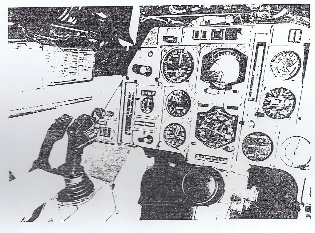
The 'blue' electrical signalling system for elevons was replaced by the digital control and sidestick arrangement, keeping the 'green' signalling as a safety backup. Normal rudder control system was retained, as well as the mechanical backup.
In the general arrangement of the digital control system one can see clearly the genesis of the A320 design - two computers with the software written by separate teams etc.
Pilot reaction seems to have been very favourable, the aircraft being somewhat easier to fly than the basic Concorde (which was already pretty good ....).
In particular the paper suggests that the precision with which the aircraft could be positioned was much improved.
Stick force per 'g' was pretty much the same throughout the speed range at about 7daN/g, whereas on Concorde it varies from 20 to 40 daN/g - but on a sidestick rather than a control column of course.
One problem that did show up, although not peculiar to Concorde, was the sensitivity of these systems to structural response, particularly during ground roll.
Not contained in the report, but in a side letter from Dudley, is a remark that the guy most responsible for the development of the Concorde basic system and later in charge of the Airbus system thought that these Concorde experiments were the key to the success of the A320.
'Nuff said!
CliveL
Subjects
Airbus
Elevons
Rudder
Sidestick
Simulator
Trim
Links are to this post in the relevant subject page so that this post can be seen in context.
Reply to this quoting this original post. You need to be logged in. Not available on closed threads.
June 21, 2011, 08:29:00 GMT
permalink Post: 6526453
It was done at just about the time that Concorde development was being abandoned, but had anyone seriously contemplated a Concorde 2 then ths would certainly have figured in the design.
Subjects: None
No recorded likes for this post (could be before pprune supported 'likes').Reply to this quoting this original post. You need to be logged in. Not available on closed threads.
June 21, 2011, 18:50:00 GMT
permalink Post: 6527665
They were certainly looking to study control laws that allowed flight at very aft CGs to increase aircraft performance, so yes, this was a CCV exercise, but they were also seeking experience with digital control and system architectures that could be transferred to other active control applications.
The 'sidestick' arrangement was virtually a complete A320 style arrangement using two computers and digital signalling throughout. For just 10 hrs they wouldn't need anything more complicated than a 'panic switch' to return control to the standard Concorde green system that was still there and available.
Clive
Subjects
AoA
C of G
Elevons
GREEN Hydraulic System
Sidestick
Links are to this post in the relevant subject page so that this post can be seen in context.
Reply to this quoting this original post. You need to be logged in. Not available on closed threads.
June 21, 2011, 22:37:00 GMT
permalink Post: 6528053
This entailed introducing artificial stability terms that would have been difficult in a purely analogue system such as the basic Concorde controls, so they decided to go digital.
Sidestick or conventional control column doesn't come into that of course - see Boeing vs AI FBW systems; but no doubt the French government saw the opportunity to get two for the price of one .....
CliveL
Subjects
Boeing
FBW (Fly By Wire)
Sidestick
Links are to this post in the relevant subject page so that this post can be seen in context.
Reply to this quoting this original post. You need to be logged in. Not available on closed threads.
June 22, 2011, 06:04:00 GMT
permalink Post: 6528482
Subjects: None
No recorded likes for this post (could be before pprune supported 'likes').Reply to this quoting this original post. You need to be logged in. Not available on closed threads.
June 23, 2011, 05:53:00 GMT
permalink Post: 6530802
if restricted to 250kts (way below min drag) you'd get pretty poor rates of climb - about 1000fpm if you were lucky
Wow, that's pretty bad. You'd figure with a T/W ratio of around 0.40 you'd do far better than most other aircraft.
Subjects
Brian Calvert
Noise Abatement
Links are to this post in the relevant subject page so that this post can be seen in context.
Reply to this quoting this original post. You need to be logged in. Not available on closed threads.
December 05, 2011, 15:45:00 GMT
permalink Post: 6843825
CliveL
Subjects
Intakes
Vortex
Links are to this post in the relevant subject page so that this post can be seen in context.
Reply to this quoting this original post. You need to be logged in. Not available on closed threads.
December 05, 2011, 16:55:00 GMT
permalink Post: 6843973
To be honest, it was all a long time ago

#4 intake was marginally worse than #1 in several ways. Obviously this particular problem was linked to the engine face distortion pattern and may have been associated with the combination of the 'handedness' of the incoming vortex with the non-radial inlet guide vanes which together could have given some subtle variations in distortions between sides. But it was all pretty fine drawn stuff, and the problem disappeared by 60 kts or thereabouts.
CliveL
Subjects
Intakes
Vortex
Links are to this post in the relevant subject page so that this post can be seen in context.
Reply to this quoting this original post. You need to be logged in. Not available on closed threads.
January 26, 2012, 16:39:00 GMT
permalink Post: 6982204
The aircraft was dynamically stable (just) because it had natural pitch damping, but in practice to give good handling qualities some artificial damping was required via the autostabiliser.
Subjects
Expansion
Intakes
Links are to this post in the relevant subject page so that this post can be seen in context.
Reply to this quoting this original post. You need to be logged in. Not available on closed threads.