January 27, 2012, 09:49:00 GMT
permalink Post: 6983492

Sure it had electrically signalled controls, but this is 1960s technology - it was (sshhh) an analogue system. No "control laws", just a direct relationship between stick and surface - the autostabiliser signals (also analogue) were just added to the stick commands.
The only bit of digital control on the airplane was in the hybrid intake control system.
Subjects
Intakes
Links are to this post in the relevant subject page so that this post can be seen in context.
Reply to this quoting this original post. You need to be logged in. Not available on closed threads.
February 03, 2012, 18:31:00 GMT
permalink Post: 6997785
Thanks.
Also, how was the flow re-compressed at the tail? What is the aerodynamic explanation of this?
As the intakes produced shocks, what about other protruberances such a aerials and drain masts etc? Did these also produce (small) shocks?[unquote]
I was generalising a bit and referring to the shocks as heard on the ground which take the form of a classic 'N' wave. This is a sudden rise in static pressure followed by a drop in static pressure to below atmospheric and then another sharp pressure rise. In supersonic flow any increase in static pressure is associated usually described as some sort of compression and conversely a drop in static pressure as an expansion. Since this happens over the region where the wing sits I described it as an expansion field over the wing.
The N wave is OK for the 'far field' shock characteristics, but as you hint, the flow near the aircraft is more complex than that - all the separate shocks gradually. merge into the bow and tail shocks. In the near field all the aerials, drain masts etc have their own little shock waves of course.
I have never seen a completely satisfactory explanation for the drop in static pressure, but if you will accept a much simplified description .....
I think there are two parts to the explanation.
The pressure over the upper wing surface will be below atmospheric static in the usual sense when lift is being generated - this will depend on the amount of lift (and hence weight)
Besides that there is a term related to the volume of the aircraft. One graphic description I have seen is that flying along at 2.0M the aircraft 'tears a hole' in the atmosphere that the surrounding air, being limited to 1.0M cannot fill. Consequently there is a drop in static pressure around the airframe. When the aircraft is past the 'void' is filled up and the resulting rapid increase in static pressure goes with the rearmost shock. This tail shock is sometimes described as the rarefaction shock.
This may not be scientifically accurate, but it satisfies me

CliveL
Subjects
Expansion
Intakes
Links are to this post in the relevant subject page so that this post can be seen in context.
Reply to this quoting this original post. You need to be logged in. Not available on closed threads.
February 03, 2012, 18:40:00 GMT
permalink Post: 6997796
Subjects: None
No recorded likes for this post (could be before pprune supported 'likes').Reply to this quoting this original post. You need to be logged in. Not available on closed threads.
February 04, 2012, 11:51:00 GMT
permalink Post: 6998987
CliveL, are there any documented records of the trials in "Boom Alley" we could use to settle some of the issue? Unquote:
Christiaan, there isn't anything particular to "Boom Alley", but there is enough data around to quantify the issue.
SSD, you were quite right when you said that the shock waves diverge as they get farther from the aircraft; that could be as much as 25% of the aircraft length at the ground. Near the aircraft the rise time would be proportional to length/speed of sound.
To cut a long story short, plotting all the available data leads to a pretty good expression for the rise time:
T = 0.011*LOA + 0.0001*FL
To give you a feel for the numbers, the measured value for an F18 at FL600 is 0.18 secs, for Concorde at FL520 about 0.25 secs or for an F104 at FL190 0.08 secs.
After that it would depend on your own perceptions I think, but I could easily envisage either a single or double bang for a fighter size aircraft depending on altitude.
Subjects
FL600
Sonic Boom
Links are to this post in the relevant subject page so that this post can be seen in context.
Reply to this quoting this original post. You need to be logged in. Not available on closed threads.
February 05, 2012, 21:58:00 GMT
permalink Post: 7001838
The intention was to give some forward facing area (at low speed) so that the LE suction had something to work on and give "LE thrust". The AoA for vortex generation would have been delayed, but the net effect was to reduce TO drag and hence power required in noise abatement climb. For cruise the LE went back to its normal position of course.
The original prototype had a similar LE droop to the Concorde 'B' (but a bit less extreme). It was changed when it was found that the droop generated an underwing vortex at low AoA (towards zero 'g') at supersonic speeds and that this vortex went down the intake with unpleasant effects on engine face distortion. This could be avoided with the moveable LE.
Subjects
AoA
Intakes
Noise Abatement
Vortex
Vortex AoA
Links are to this post in the relevant subject page so that this post can be seen in context.
Reply to this quoting this original post. You need to be logged in. Not available on closed threads.
February 18, 2012, 18:45:00 GMT
permalink Post: 7030632
I don't envy you your self imposed task, you will I'm afraid find it quite difficult to get any detailed drawings as they were long ago buried in the archives of two now non-existent companies - Sud Aviation and British Aircraft Corporation.
The best source of overall structure drawings I have seen is that on the HeritageConcorde.com site. which also gives some explanations of the structural concepts. The Haynes Concorde Owners Workshop Manual also has some interesting data. One problem is that the loading conditions on the various bits of the wing varied so much and the whole thing was so finely optimised for weight saving that there are many different structural concepts used.
You (and others here) may find a 1999 lecture given by Dudley Collard (a much respected Concorde design engineer) of interest. You can find it at www.svfw.ch/Archiv/ConcordeDev.pdf
Felicitations!
Last edited by CliveL; 18th February 2012 at 18:47 . Reason: spelling
Subjects
Haynes guide to Concorde
Links are to this post in the relevant subject page so that this post can be seen in context.
Reply to this quoting this original post. You need to be logged in. Not available on closed threads.
April 06, 2012, 19:42:00 GMT
permalink Post: 7121591
SORRY - senior moment - this should have been posted on another thread!

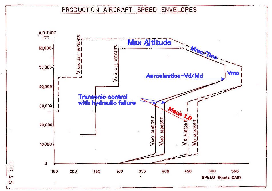
To be honest I can't remember exactly why 530 kts was chosen for the supersonic Vmo, but it was probably the best climb speed.
Mmo/Tmo was limited by a combination of intake and structural temperature.
The 'cut-off' in the sloping/530 kts boundary was, if I remember correctly, to avoid a minor aeroelastic problem at the Vd/Md condition one arrived at from that corner.
The variation of Vmo with weight was a device which, when associated with the CG corridor, allowed the aircraft to meet the manoeuvre requirements when flying on half hydraulics.
400 kts CAS gave 0.93M at around 28000 ft if I recall correctly, which was just below drag rise and gave optimum subsonic cruise performance
Last edited by Jetdriver; 21st April 2012 at 00:33 .
Subjects
C of G
Intakes
Vmo
Links are to this post in the relevant subject page so that this post can be seen in context.
Reply to this quoting this original post. You need to be logged in. Not available on closed threads.
April 27, 2012, 22:06:00 GMT
permalink Post: 7159745
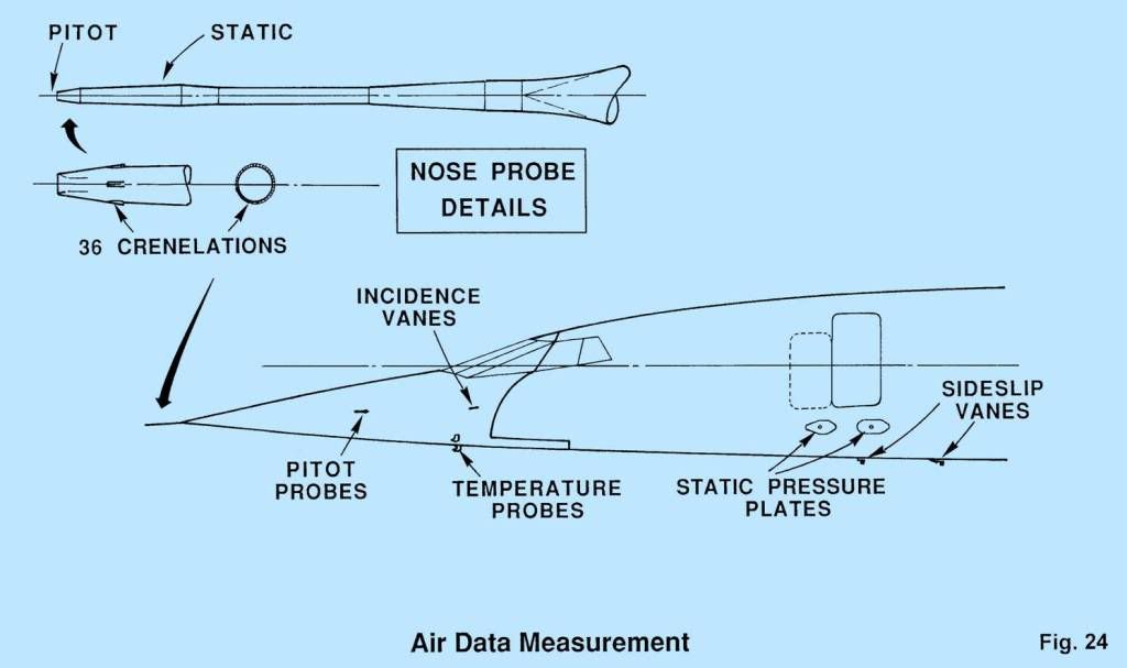
SSD:- this answers your question on where the TAT probes were located. Strictly, you don't need temperature to calculate Mach as it is independent of temperature when expressed in EAS (or CAS) terms.
Shane:
The "crown modifications" were external straps to be applied to the upper part of the fuselage to extend its life in those areas which had been designed to safe life concepts - basically the Aerospatiale bits since BAe designed their bits according to damage tolerance rules. It wasn't a small job, but I'm afraid I can't tell you how many aircraft were modified.
Subjects
Aerospatiale
Crown Modification
TAT (Total Air Temperature)
Links are to this post in the relevant subject page so that this post can be seen in context.
Reply to this quoting this original post. You need to be logged in. Not available on closed threads.
April 28, 2012, 10:15:00 GMT
permalink Post: 7160324
There was, so far as I recall, no measure of skin temperature - the aircraft limit (Tmo) was simply based on a measured TAT of 400 degK. The implied limits on skin temperature at various points were built into the design cases.
Subjects
Skin Temperature
TAT (Total Air Temperature)
TMO (Temprature Max Operating)
Links are to this post in the relevant subject page so that this post can be seen in context.
Reply to this quoting this original post. You need to be logged in. Not available on closed threads.
April 28, 2012, 21:49:00 GMT
permalink Post: 7161147
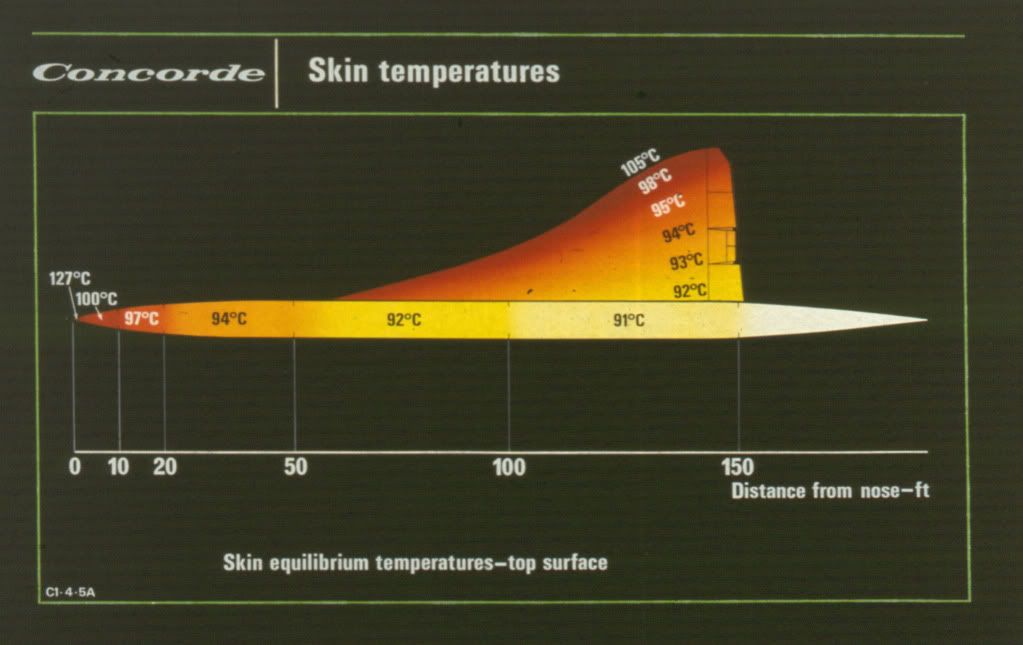
Not exactly skin temperature, just the maximum temperature on the nose. The rest of the aircraft was cooler.
Subjects
Skin Temperature
Links are to this post in the relevant subject page so that this post can be seen in context.
Reply to this quoting this original post. You need to be logged in. Not available on closed threads.
April 29, 2012, 08:11:00 GMT
permalink Post: 7161595
And.. How was static temp readout derived?
They are mounted off the skin and in freestream, so they measure the same temperature as would a probe on the nose.
Somewhere near the nose (not exactly on it, as the aircraft flies with a small AoA) there will be a 'stagnation' streamline where the oncoming air is brought to rest. At this point the skin temperature will be equal to the stagnation temperature (TAT). Behind that it gets more complicated! The skin temperature would depend on SAT, local Mach No, local skin friction coefficient (Mach and Re dependent, so varies with distance from nose), amount of heat radiated into space (paint colour!) and the amount of structure available to conduct heat away from the skin into the fuel (so roughly varying with thickness/chord and fuel distribution perhaps?
Static temperature and total temperature are related by a simple expression:
TAT = SAT *(1+0.2m^2) all in deg K
So in the troposphere at ISA +5 and Mach 2, SAT = 222 and TAT = 400.
Subjects
AoA
Skin Temperature
Stagnation Point
TAT (Total Air Temperature)
Links are to this post in the relevant subject page so that this post can be seen in context.
Reply to this quoting this original post. You need to be logged in. Not available on closed threads.
May 09, 2012, 21:12:00 GMT
permalink Post: 7180741
Henri was one of my favourite Frenchmen. Not only was he a very fine engineer but also a very nice guy.
Maybe stretching it a bit to describe him as the creator of Concorde, but he was certainly one of the principal midwives on the French side.
Subjects: None
No recorded likes for this post (could be before pprune supported 'likes').Reply to this quoting this original post. You need to be logged in. Not available on closed threads.
June 01, 2012, 19:57:00 GMT
permalink Post: 7221648
It would be true to say that Chadwick was one of the first outside Germany to use it, but that was essentially with a rounded leading edge, which is a very different animal from the slender delta with a sharp leading edges to deliberately produce strong vortices which give non-linear lift at high AoA.
That concept was definitely the brainchild of Kuchemann and his team (mostly fellow Germans
 ) at RAE Farnborough.
Subjects
AoA
RAE Farnborough
Links are to this post in the relevant subject page so that this post can be seen in context.
Reply to this quoting this original post. You need to be logged in. Not available on closed threads.
June 25, 2012, 15:13:00 GMT
permalink Post: 7261526
It would take a book to answer your questions properly. Luckily someone has already written it - try to get hold of Ken Owen's "Concorde New Shape in the Sky" ISBN 0 7106 0268 5. It is an excellent account of the genesis and development of the machine that drove my life for 25 years.
You are right - it was a political agreement, but politics after all the art of agreeing what is possible, and we are talking of the UK and France of the 1950s. No way that either of those two proud countries was going to let the other have the lion's share of the kudos and fun of developing and flying the world's first supersonic airliner. Fun? yes, exciting, challenging, exhausting but definitely fun.
and no way it was going to be other than an equal split.
But one can easily argue that it was arranged so that each country contributed the best it had to offer. The actual split was 50/50 on total costs, but arranged so that the UK had 60% of powerplant and 40% airframe. At the time, France had nothing to compare with the Olympus as an engine suitable for supersonic cruise, so that was logical. Out of our 40% on airframe we had responsibility for the intake and for powerplant/airframe integration. But when it came down to brass tacks Onera had a more flexible intake design than anything we Brits had to offer, and later in the project the "TRA" nozzle also came from France. We can take a lot of credit for melding these into a very successful powerplant, but I think it fair to say that each country did, in fact, contribute the best it had to offer.
As for fair shares for all, well all I can say is that there was more than enough work to go around

Subjects
Intakes
Nozzles
Links are to this post in the relevant subject page so that this post can be seen in context.
Reply to this quoting this original post. You need to be logged in. Not available on closed threads.
June 27, 2012, 09:10:00 GMT
permalink Post: 7264296

That's because of my age not my profession - real aerodynamicists get around all that by using non-dimensional quantities like CL and Cd.
IIRC, the drawings were dimensioned in both units, but all threads etc were metric. Dude would know that better than I though. There was never any real difficulty with it.
Last edited by CliveL; 27th June 2012 at 09:13 .
Subjects: None
No recorded likes for this post (could be before pprune supported 'likes').Reply to this quoting this original post. You need to be logged in. Not available on closed threads.
June 27, 2012, 11:29:00 GMT
permalink Post: 7264492
Partly out of equal shares, but there was also more flight test development work than could be handled by just one aircraft in a reasonable timescale, and each partner had their own sphere of responsibility to cover so if you have to have two airframes it made some sense to have one each.
Subjects: None
No recorded likes for this post (could be before pprune supported 'likes').Reply to this quoting this original post. You need to be logged in. Not available on closed threads.
July 10, 2012, 17:26:00 GMT
permalink Post: 7288167
All flight tests reveal unforeseen problems! This could result in a pause in the prototype/pre-production flight test programme whilst the test aircraft was being modified, but this didn't delay build of later vesrions.
Subjects: None
No recorded likes for this post (could be before pprune supported 'likes').Reply to this quoting this original post. You need to be logged in. Not available on closed threads.
August 01, 2012, 18:47:00 GMT
permalink Post: 7337715
Subjects
Intakes
Links are to this post in the relevant subject page so that this post can be seen in context.
Reply to this quoting this original post. You need to be logged in. Not available on closed threads.
August 04, 2012, 11:43:00 GMT
permalink Post: 7341902
I don't think there is any published explanation, but maybe this will help.
Basically the problem with #4 intake was that it was on the RHS of the airplane. We are talking about low speed right? and especially zero forward speed when the engine is trying to suck as much air as it can get from wherever it can get it. That means that the induced angle of attack on all the intake leading edges is going to be high.
The best drawing I can find that shows the flow into the right hand pair is this
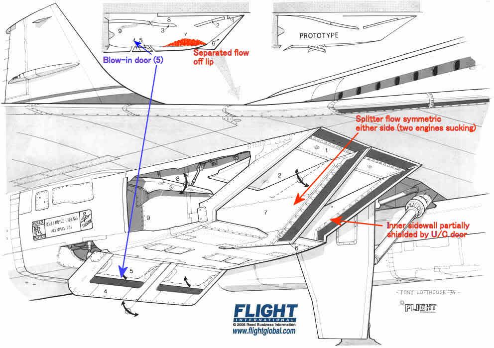
The intake leading edges were all sharp, so the flow would separate if subjected to a high AoA. The upper lip was protected a little by the wing leading edge, and we were obliged to modify the prototype LE ahead of the intakes to prevent underwing vortices developing at low AoA in cruise which also helped a bit.
The lower lip had a substantial separated flow 'bubble' at low forward speed as shown in red, but this cleared up quite quickly as the aircraft gathered speed. It was'cured' by the blow-in doors.
The inner sidewalls were shielded by the landing gear doors, so the AoAs on the sidewall on that side were quite modest.
The splitter was of course subject to equal flow demands on either side so the flow over that was pretty well symmetric.
That leaves the two outer sidewalls which, look for all the world like highly swept delta wings with sharp LEs mounted vertically.
Like all such wings when operated at high AoA they develop powerful vortices on the 'leeward' side. Looking back towards the engine the vortex on #4 engine was anticlockwise and that on #1 was clockwise. [Hope I got that one the right way round
]
The OL593 rotates clockwise looking aft so the induced incremental AoA on the compressor blades was different on #1 and #4. The difference was enough to trigger some mild blade vibration - hence the rpm restriction until the intake capture was good enough to reduce the vortex strength.
Subjects
AoA
Intakes
Landing Gear
Vortex
Links are to this post in the relevant subject page so that this post can be seen in context.
Reply to this quoting this original post. You need to be logged in. Not available on closed threads.
September 01, 2012, 16:50:00 GMT
permalink Post: 7390685
@ The Late XV105
Pure speculation - a drain hole with some sort of guide to deflect the fluid away from some other part?
Subjects: None
No recorded likes for this post (could be before pprune supported 'likes').Reply to this quoting this original post. You need to be logged in. Not available on closed threads.