September 01, 2012, 18:36:00 GMT
permalink Post: 7390838
Subjects
Noise Abatement
Links are to this post in the relevant subject page so that this post can be seen in context.
Reply to this quoting this original post. You need to be logged in. Not available on closed threads.
September 02, 2012, 10:56:00 GMT
permalink Post: 7391786
I can't give you much detail I'm afraid - as JT said a few posts ago:
Subjects
Fatigue
Links are to this post in the relevant subject page so that this post can be seen in context.
Reply to this quoting this original post. You need to be logged in. Not available on closed threads.
September 02, 2012, 11:58:00 GMT
permalink Post: 7391877

Last edited by CliveL; 2nd September 2012 at 11:58 .
Subjects: None
No recorded likes for this post (could be before pprune supported 'likes').Reply to this quoting this original post. You need to be logged in. Not available on closed threads.
September 02, 2012, 12:02:00 GMT
permalink Post: 7391881
Subjects: None
No recorded likes for this post (could be before pprune supported 'likes').Reply to this quoting this original post. You need to be logged in. Not available on closed threads.
September 02, 2012, 12:06:00 GMT
permalink Post: 7391887
Subjects
Vortex
Links are to this post in the relevant subject page so that this post can be seen in context.
Reply to this quoting this original post. You need to be logged in. Not available on closed threads.
October 27, 2012, 09:40:00 GMT
permalink Post: 7488997
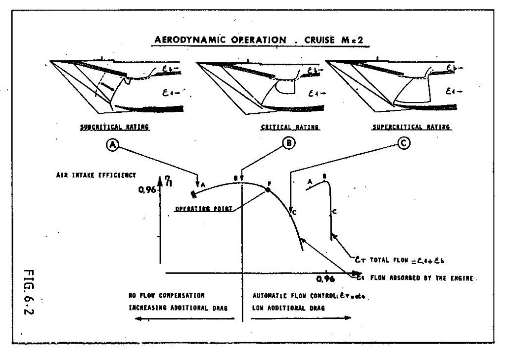
In normal operation (centre picture), the flow in the upper half of the intake was supersonic with a normal shock as required to decelerate to subsonic conditions. In the lower half the flow was decelerated to just sonic by the cowl shock. If the engine demand increased the region of supersonic flow got bigger until it nearly filled the intake (right hand picture).
The small reversed "D" zone just below the bleed slot is the supersonic region. The bleed flow entered the bleed aft of the normal shock.
Last edited by CliveL; 27th October 2012 at 09:44 .
Subjects
Bleed Air
Intakes
Links are to this post in the relevant subject page so that this post can be seen in context.
Reply to this quoting this original post. You need to be logged in. Not available on closed threads.
October 28, 2012, 08:16:00 GMT
permalink Post: 7490288
As you say, a complex subject!
Maybe the missing link is that a plane shock is not the only way to decelerate through Mach 1.0. If the nose of a body is blunt, or if the angle you are trying to turn the flow through is too big then the shock wave becomes detached from the leading edge of the body. The bit of the shock on the 'cusp' is then actually a very strong plane (normal) shock and the flow immediately behind that part is subsonic. In the case of a sharp surface with a large tuning angle this subsonic flow allows air to escape from the high pressure side of the surface to the low pressure side. This would be the case for example if the flow onto the leading edge of an intake hit it at too big an angle.
Supersonic intakes come in two basic guises - external compression and internal compression. The ramjet intakes you have been reading about are the latter type in which all the deceleration/compression takes place inside the intake. In these designs the final compression is through a normal shock situated at the minimum area 'throat' of the intake where the flow is close to Mach 1.0. This flow is delicately balanced and if some engine disturbance causes the shock to move into the converging supersonic bit of the intake the whole shock system can be expelled giving all sorts of problems (inlet unstart). Generally they are used for high Mach numbers where their higher theoretical efficiency and low external/spillage drag count for more than the additional control system complexity and performance requirements.
In external compression intakes (a simple pitot intake would be an extreme example), all the compression is done by a system of shock waves that sit outside the intake. These intakes are less efficient than internal compression intakes and they also spill a lot of air which produces external drag. Usually restricted to low supersonic Mach numbers.
Concorde's intake was a "mixed compression" design which had some features of each type. At low engine mass flow demands the flow coming on to the cowl lip could be at too great an angle to maintain attached shock waves so it behaved a bit like that described earlier. You can see this most clearly in the left hand picture where the lower efficiency and higher spillage can be seen in the graph of efficiency against intake capture (epsilon). In this state the intake behaved more like an external compression type and there was no appreciable final normal shock.
At high engine demand the angle of flow hitting the cowl was such that the shock waves remained attached and the intake functioned more like an internal compression design. Again you can see this in the right hand picture which shows most of the intake throat covered by a normal shock and in the graph where total intake flow (engine plus bleed) is constant.
On condition there was a bit of each, but since it was designed to minimise spillage you cannot see the detachment of the cowl lip shock at the scale of the diagram.
Hope this is helpful rather than additionally confusing!
PS: Looking at the centre picture again, it occurs to me that the curved shock running from the lip back and up to the reversed "D" would actually be normal to the approaching local flow which was being turned by the ramps and the isentropic compression. This would be the shock you are looking for to decelerate the flow to subsonic conditions. In other words the intake was functioning as an external compression design over this part.
Last edited by CliveL; 28th October 2012 at 08:28 .
Subjects
Bleed Air
Intakes
Links are to this post in the relevant subject page so that this post can be seen in context.
Reply to this quoting this original post. You need to be logged in. Not available on closed threads.
February 23, 2013, 09:06:00 GMT
permalink Post: 7710332
Once it was decided to go, I would say that the system requirements were largely driven by the difficulty of the task - more a question of finding out how to make it work than of optimising. The overall aircraft requirements were driven by the engineers, but criticised by the potential customer airlines in regular meetings.
Safety requirements were specified in a completely new airworthiness code - a sort of comprehensive set of special conditions, which were generally more severe than the subsonic codes of the time. Concorde, for example, was, AFAIK , the first civil aircraft to be certificated against the requirements that now exist as 25.1309.
But nobody really knew what to write for supersonic flight and, in particular, the transition from subsonic, so to some extent one made it up as one went along, using prudent common sense and engineering judgement. Fuel system transfer rates for example had to match a requirement that it should be possible to abandon the acceleration at any point and return safely to subsonic conditions - and the deceleration was much quicker than the acceleration!
 Supersonic testing mainly at 1/30 scale; low speed 1/18. The biggest model was a 1/6 scale half model used mainly for icing tests. Isolated intake tests, IIRC, about 1/10 scale, but we did have a full scale intake operating in front of an Olympus 593 at Mach 2.0 in Cell 4 at NGTE Pyestock.
Subjects
Intakes
Olympus 593
Links are to this post in the relevant subject page so that this post can be seen in context.
Reply to this quoting this original post. You need to be logged in. Not available on closed threads.
October 14, 2013, 15:06:00 GMT
permalink Post: 8098479
ref heritageconcorde.com
Does anyone have any details on the 'joint' development alluded to above?
The problem apparently was that flame stabilisation operating in "contingency" rating was sensitive to the point that every engine had to be checked, so there was a lot of engine plus reheat testing, most of which was done at Patchway. The solution was addition of some form of 'spike' at various points on the spray bar (my informant wasn't very specific). It sounded like a sort of vortex generator cum chine that gave the flame somewhere to latch onto. The development process was, as you suggested, a joint activity.
Subjects
Afterburner/Re-heat
Rolls Royce
Vortex
Links are to this post in the relevant subject page so that this post can be seen in context.
Reply to this quoting this original post. You need to be logged in. Not available on closed threads.
October 17, 2013, 11:15:00 GMT
permalink Post: 8103250
I've just started reading it, and it's pure Ted (and Ann)
Do buy it - it is probably the most amusing (and human) book on Concorde you will ever read. Best seven quids worth I have spent for a long time.
Update: I have now finished it - I couldn't put it down. Definitely autobiographical, but worth buying for the Concorde bits alone. Maybe I'm biased as I share many of his memories. Perhaps UK readers will appreciate the non-Concorde bits more.
Last edited by CliveL; 17th October 2013 at 19:46 . Reason: update
Subjects: None
No recorded likes for this post (could be before pprune supported 'likes').Reply to this quoting this original post. You need to be logged in. Not available on closed threads.
October 18, 2013, 19:12:00 GMT
permalink Post: 8106029
Subjects
AICS (Air Intake Control System)
Airbus
Filton
Pressurisation
Links are to this post in the relevant subject page so that this post can be seen in context.
Reply to this quoting this original post. You need to be logged in. Not available on closed threads.
October 23, 2013, 13:49:00 GMT
permalink Post: 8113333
I suspect the zero bypass Ol 593 would take less time to spool up than todays high bypass engines.
Subjects
Airbus
Olympus 593
Links are to this post in the relevant subject page so that this post can be seen in context.
Reply to this quoting this original post. You need to be logged in. Not available on closed threads.
January 08, 2014, 07:53:00 GMT
permalink Post: 8252886
Subjects
Intakes
Links are to this post in the relevant subject page so that this post can be seen in context.
Reply to this quoting this original post. You need to be logged in. Not available on closed threads.
February 20, 2014, 08:09:00 GMT
permalink Post: 8328956
SSD
I'm afraid I can't tell you what they actually do, but I am pretty sure they aren't part of the anemometry because those static ports are "pepperpots" mounted on specially machined and jigged flat plates. This was necessary because static pressure at Mach 2 is sensitive to local skin waviness.
Do you have a photo?
Subjects
Static Ports
Links are to this post in the relevant subject page so that this post can be seen in context.
Reply to this quoting this original post. You need to be logged in. Not available on closed threads.
February 22, 2014, 13:04:00 GMT
permalink Post: 8333372
I know they aren't anything to do with AICUs but seeing where they are located and looking at Bellerephon's diagram I would think they are reference static ports for the air conditioning system - needed to monitor differential pressure.
Dude where are you when we need you?
Subjects
AICU (Air Intake Control Computer)
Static Ports
Links are to this post in the relevant subject page so that this post can be seen in context.
Reply to this quoting this original post. You need to be logged in. Not available on closed threads.
March 04, 2014, 17:51:00 GMT
permalink Post: 8352423
PM me and I will send you something that might help
Subjects: None
No recorded likes for this post (could be before pprune supported 'likes').Reply to this quoting this original post. You need to be logged in. Not available on closed threads.
June 29, 2014, 16:12:00 GMT
permalink Post: 8542535
Anyone know the story on these inlets?
They were an attempt to avoid the mechanical complexities of the prototype double hinged 'barn door' combined dump door/auxiliary intake by having several 'blow-in' vanes set in the door which were locked when the door was operated as a dump door.
Had their own set of mechanical problems and the idea was abandoned in favour of a single blow-in door (production solution)
Subjects
Intakes
Links are to this post in the relevant subject page so that this post can be seen in context.
Reply to this quoting this original post. You need to be logged in. Not available on closed threads.
April 05, 2015, 08:55:00 GMT
permalink Post: 8933615
There was a certification requirement for descent time from FL600 down to FL100 if I recall correctly. Can't remember the value though. In flight reverse was developed to trim some fraction of a minute off the time to get inside the requirement
@ a_q
Not sure what you mean by a "leaky" intake. At about 2.2M the first shock would hit the intake lower lip and from that point on the total intake mass flow was frozen. Increased engine mass flow could only be obtained by reducing bleed flow and that gave higher engine face flow distortions driving the engine towards surge and lower intake recovery. So engine mass flow was effectively fixed also.
Then the amount of "dry" fuel which could be added was limited because the higher Mach number increased the engine entry temperature but the maximum turbine entry temperature was fixed.
You could add thrust by using reheat, but you would not get as much as you would like because the final nozzle, being designed for 2.0M would be too small for optimum efficiency at higher Mach numbers.
Overall, IIRC we got to 2.23M in flight test. If you pushed me I would say it might be possible with reheat etc to get to 2.25 or 2.26M, but it would be a blind guess!
Subjects
Afterburner/Re-heat
Bleed Air
Engine surge
FL600
Intakes
Nozzles
Trim
Links are to this post in the relevant subject page so that this post can be seen in context.
Reply to this quoting this original post. You need to be logged in. Not available on closed threads.
April 08, 2015, 08:02:00 GMT
permalink Post: 8936540
Ah yes, page 55 from 4 years ago ...... It's my age you know!
What threw me was your reference to a leaky intake - on 101 it was all the nacelle aft of the intake that leaked not the intake itself
Subjects
Intakes
Links are to this post in the relevant subject page so that this post can be seen in context.
Reply to this quoting this original post. You need to be logged in. Not available on closed threads.
April 09, 2015, 08:24:00 GMT
permalink Post: 8937544
Yes they did. I tried to post a photograph but the Dropbox link doesn't seem to work any more (neither does the "quote" icon)
Subjects: None
No recorded likes for this post (could be before pprune supported 'likes').Reply to this quoting this original post. You need to be logged in. Not available on closed threads.