April 05, 2011, 08:23:00 GMT
permalink Post: 6351256
1) The first shock was generated from the top lip of the intake
2) A second shock is generated from the fwd ramp hinge
3) A third isentropic fan shock is generated from the progressively
curved section of the fwd ramp
4) A 4th shock was generated fron the bottom lip
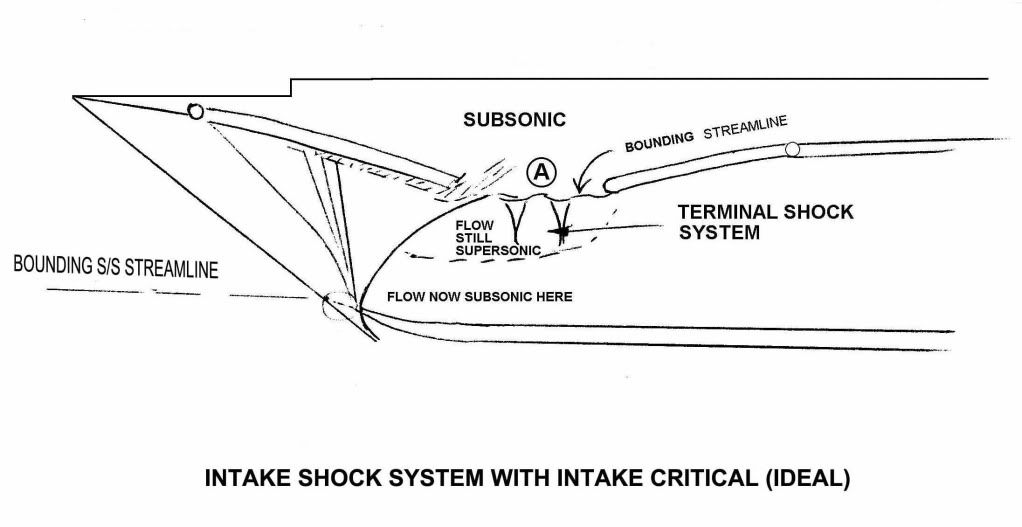
5) A terminal shock system is generated by the coalescence of
still supersonic and now subsonic air at the upper section of the ramp
area.
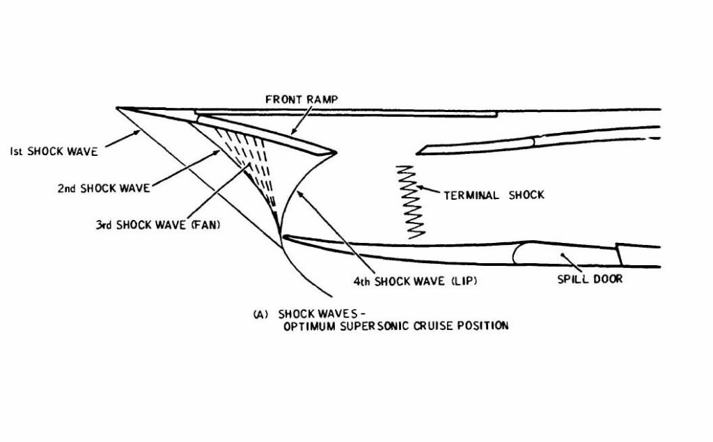
Hopefully these two diagrams will help. The first hand illustration above gives the 'theoretical' shock pattern and the second below gives an illustration of practical flows within the inlet. Both assume critical operation at Mach 2.
I hope all this blurb helps
Best regards
Dude

Last edited by M2dude; 5th April 2011 at 08:35 .
Subjects
Intakes
Shockwave
Links are to this post in the relevant subject page so that this post can be seen in context.
Reply to this quoting this original post. You need to be logged in. Not available on closed threads.
April 05, 2011, 19:09:00 GMT
permalink Post: 6352404
CliveL

(As always you are of course 100% on the bal. And what do aerodynamisits know about aerodynamics anyway

 ).
).
Best regards
Dude
Subjects
Bleed Air
Links are to this post in the relevant subject page so that this post can be seen in context.
Reply to this quoting this original post. You need to be logged in. Not available on closed threads.
April 06, 2011, 06:17:00 GMT
permalink Post: 6353241
It seems a million years ago when we fitted this high presicion lump of alluminium. (Hang on a minute, it WAS
 ).
).
Best regards
Dude
Subjects
Afterburner/Re-heat
INS (Inertial Navigation System)
Links are to this post in the relevant subject page so that this post can be seen in context.
Reply to this quoting this original post. You need to be logged in. Not available on closed threads.
April 07, 2011, 12:00:00 GMT
permalink Post: 6355821
Subjects
Intakes
Links are to this post in the relevant subject page so that this post can be seen in context.
Reply to this quoting this original post. You need to be logged in. Not available on closed threads.
April 08, 2011, 07:13:00 GMT
permalink Post: 6357473
One of the real beauties of the Concorde intake was that it was completely self-startiing, and so unstarts as such were never heard of.
Regarding the vibrations thing, here is my post #80:
Subjects
Intakes
LP Compressor
N1 (revolutions)
Rolls Royce
Vortex
Links are to this post in the relevant subject page so that this post can be seen in context.
Reply to this quoting this original post. You need to be logged in. Not available on closed threads.
April 08, 2011, 10:53:00 GMT
permalink Post: 6357778
Subjects: None
No recorded likes for this post (could be before pprune supported 'likes').Reply to this quoting this original post. You need to be logged in. Not available on closed threads.
April 08, 2011, 16:29:00 GMT
permalink Post: 6358344
Last edited by Jetdriver; 10th April 2011 at 09:23 .
Subjects
Afterburner/Re-heat
Braking
N1 (revolutions)
Transonic Acceleration
Links are to this post in the relevant subject page so that this post can be seen in context.
Reply to this quoting this original post. You need to be logged in. Not available on closed threads.
April 09, 2011, 07:43:00 GMT
permalink Post: 6359455
 ).
).
That was interesting stuff about the P38, I must admit I'd not heard that one. (Makes sense I suppose though, provided that the engine can be easily be re-positioned in such a way).
Last edited by M2dude; 9th April 2011 at 11:29 .
Subjects
Avionics
Links are to this post in the relevant subject page so that this post can be seen in context.
Reply to this quoting this original post. You need to be logged in. Not available on closed threads.
April 09, 2011, 11:39:00 GMT
permalink Post: 6359798
Subjects: None
No recorded likes for this post (could be before pprune supported 'likes').Reply to this quoting this original post. You need to be logged in. Not available on closed threads.
April 17, 2011, 04:37:00 GMT
permalink Post: 6396260
I worked on 202 personally quite a bit during the mid to late 70's, but she never remotely 'felt' like a real production aircraft. Even aircraft 204 (G-BOAC) in her pre-route proving days was a radically different beast. (The OAC post route-proving modifications although at system level were quite extensive, these were miniscule in comparison to the differences between 202 and what we like to call 'the REAL Concorde'. Don't get me wrong, 202 did some absolutely stirring work in terms of route-proving and certification trials, and the restoration done at Brooklands is most impressive indeed, but she is and always was, nothing other than a test aircraft. She was no more a production airframe in reality than the pre-production aircraft 102, and I'm afraid that anyone thinking that she is anying other than this is truly deluding themselves my friend.
I'm sorry if this reality is dissapointing steve-de-s, but if you want to see a Concorde that is truly representative of what the aircraft was really all about I suggest that you pop up to either Manchester or East Fortune. (The only airliner museums in the UK now open to public viewing). The Manchester exhibit in particular is truly superb and beautifully kept by some great people, and shows you exactly what Concorde, THE AIRLINER was actually like, rather than just seeing a test specimin. (A superb specimin 202 indeed she was, but this is ALL she ever was, a test specimin).
Best regards
Dude
Last edited by M2dude; 17th April 2011 at 07:09 .
Subjects
Brooklands
G-BOAC
Intakes
MEPU (Monogol Emergency Power Unit)
Links are to this post in the relevant subject page so that this post can be seen in context.
Reply to this quoting this original post. You need to be logged in. Not available on closed threads.
April 18, 2011, 05:06:00 GMT
permalink Post: 6397913
There were several semi-structural and 'heavy' system components that were robbed by BA (I removed some stuff myself in the mid 80's and early 90's), but the fact remains that there were massive system differences that could never be reconciled by simple 'mods'. The fact also remains that she was a 5100 variant aircraft and not a 5101/5102 variant (or a 100 series aircraft either) and was significantly D-I-F-F-E-R-E-N-T to the 'real' aircraft, the airliners. I was THERE and I SAW the differences myself enough times for goodness sake, and the fact remains she was NEVER an airliner and never had any real prospect of being one. (But as I said before, she was a wonderful TEST specimin and did some stirling work). Brooklands really has a lot to offer the visitor as an exhibit I suppose but if you want to see Concorde THE AIRLINER then you really need to go elsewhere. Manchester in the only place where you can now see an intact production series Concorde in the UK and as I said before is NOW lovingly cared for by some brilliant people.
Regards
Dude
Last edited by M2dude; 18th April 2011 at 08:05 .
Subjects
British Airways
Brooklands
Fairford
Links are to this post in the relevant subject page so that this post can be seen in context.
Reply to this quoting this original post. You need to be logged in. Not available on closed threads.
April 23, 2011, 09:13:00 GMT
permalink Post: 6407386
And sorry everyone about the \xa330 cost of converting 202 into an airliner, I meant (dumb ass that I am) \xa330 MILLION.

Best regards
Dude
Subjects
British Airways
Filton
G-BFKW
G-BOAA
G-BOAB
G-BOAC
G-BOAD
G-BOAE
G-BOAF
G-BOAG
Links are to this post in the relevant subject page so that this post can be seen in context.
Reply to this quoting this original post. You need to be logged in. Not available on closed threads.
April 24, 2011, 14:09:00 GMT
permalink Post: 6409591
I would have thought that the whole venture was a proof of concept by SFENA for future implementation in the Airbus family. This excersise would have been both costly and highly complex at system level, any other reason would really have been quite daft.
Best Regards
Dude
Last edited by M2dude; 24th April 2011 at 15:08 .
Subjects
Airbus
Auto-stabilisation
Elevons
Fuel Burn
Sidestick
Vmo
Links are to this post in the relevant subject page so that this post can be seen in context.
Reply to this quoting this original post. You need to be logged in. Not available on closed threads.
April 25, 2011, 06:54:00 GMT
permalink Post: 6410658
 As we do not know what the PROPOSED flight regime was, on the part of SFENA and Aerospatiale,we also can not assume that any particular manoeuvr would not have been considered. (But as I said before, it would be great to find out the whole story).
The limited authority for roll autostabilisation (and hence Emergency Flight Control) was of course a very deliberate piece of design. (You could test the Emergency Pilot on the ground at ADC Test 2 (Which simulated several seperate overspeeds, including Vmo +20) and when you put in a roll demand (against some resistance), only the MIDDLE elevons deflected. It really looked wierd on the ICOVOL as well as outside the aircraft.
(To any chaps or chapesses who are not aware, above Vmo+20 KCAS, a system known as OUTER ELEVON NEUTRALISATION was invoked, where any input demand to the outer elevons was met by an automatic equal and OPPOSITE input, that of course completely neutralised the demand, giving a zero OUTER elevon deflection).
Best regards
Dude
Subjects
ADC (Air Data Computer)
Elevons
Vmo
Links are to this post in the relevant subject page so that this post can be seen in context.
Reply to this quoting this original post. You need to be logged in. Not available on closed threads.
June 03, 2011, 11:35:00 GMT
permalink Post: 6490820
There were a few questions regarding ground running Concorde, so here are some 'facts' as far as I recall (Wrinkled old brain permitting).
Concorde was ALWAYS ground run in the detuners at the BA Engineering base at Heathrow, with the parking brake ON. (Save idle runs on the ramp after, say, replacing a PNC actuator etc. on departure. The required high power nozzle trim run could be deferred until the aircrafts return to LHR). Sadly I can confirm that the Concorde 'Hush House' was being demolished when I was last over the engineering patch a few weeks ago, and is probably all gone now.
The detuner chocks were like nothing else you could imagine. They were HUGE steel affairs that needed wheels to be wound down in order to move into position (took a couple of guys at least to move). Once in position forward and aft of the undercarriage, the wheels would be retracted and these 'chocks' would be tension chained together. Believe me, nothing was going to move these suckers!!
Engines WERE NOT run in symmetrical pairs, but the adjacent engine always was run at idle power. The reason for this was so that there was airflow over the T1 probe of the adjacent engine, a winding in this being used by the alternate engine control lane if needs meant it might be required if the main lane failed during the engine run. The way that the aircraft was tethered meant that symmetrical high power running was not any sort of issue.
We were very mean too. In the summer the hangar doors of TBK opposite would invariably be open during the day, the challenge was to see how long it took for us to make them close the doors to shut out the din. (Like I said, Concorde engineers were mean
 ).
).
Good to be back
Best regards to all
Dude
Last edited by M2dude; 4th June 2011 at 20:03 .
Subjects
British Airways
LHR
Nozzles
Trim
Links are to this post in the relevant subject page so that this post can be seen in context.
Reply to this quoting this original post. You need to be logged in. Not available on closed threads.
June 21, 2011, 15:45:00 GMT
permalink Post: 6527294
I'd still personally like to know how the sidestick was integrated into the flying control system, I've been thinking and can not now believe that sidestick inputs could be simply input to the flying control system 'at resolver level'. Remember that the concept of the FBW system on Concorde was that resolvers were utilised as simple 4 wire synchros, and the pitch and roll axis utilised a CX/CDX/CT chain, which produced the error signal to the ESA's in the Autostab computers. Using a sidestick completely breaks up the chain, and my guess is that a seperate digital unit contained the flight rules which were summed against PFCU CT position and sidestick input would have been necessary. It is possible then that an analog output from this 'box' could be fed to the Autostab Computer ESAs and hence drive the elevons. I'm probably completely wrong, but I'd surely still love to know the truth. As you say Clive, ideal stuff for Concorde 2.
Best regards
Dude
Last edited by M2dude; 21st June 2011 at 18:53 . Reason: A fine wine may improve with age... my spelling however doesn't
Subjects
Auto-stabilisation
C of G
Elevons
FBW (Fly By Wire)
PFCU (Powered Flying Control Units)
Sidestick
Links are to this post in the relevant subject page so that this post can be seen in context.
Reply to this quoting this original post. You need to be logged in. Not available on closed threads.
June 21, 2011, 18:55:00 GMT
permalink Post: 6527670
Best Regards
Dude
Subjects
Elevons
Links are to this post in the relevant subject page so that this post can be seen in context.
Reply to this quoting this original post. You need to be logged in. Not available on closed threads.
June 28, 2011, 11:17:00 GMT
permalink Post: 6540463
Ahhh that question again. Just concentrating then on matters on the UK side of the English Channel. Prior to the Paris crash, BA was making a very healthy profit indeed on it's Concorde operation. There were some blots on the horizon that had to be overcome (Relife 2, SFAR regulation implementation, EGPWS and GPS navigation enhancement etc.) but all these things were 'doable' and under both study and disussion.
After the Paris crash came the horrible events of 9-11; around 40 regular BA Concorde passengers were tragically lost in the twin towers alone. When the aircraft returned to service in November 2001 the loads (and profitablity) were understandably taking a major hit, but as all times in her service life Concorde had the ability to weather the storm and was already bouncing back well. Unfortunately in 2003, due to some totally disgusting goings on, on the French side of the Channel, the aeroplane never got the chance to fully recover and BA services ceased in October of that year. (It is to the eternal shame of certain individuals on THIS side of the Channel that this French Disconnection was never challenged legally).
Concorde was only ever run (that is at least in the UK) for profit, but the hike in oil prices would obviously pushed up ticket prices significantly, and the massive economic downturn of last year would have certainly meant a temporary reduction in services. But in spite of all this, I firmly believe that Concorde would have weathered this storm, and would have been now earning those bucks for BA yet again.
John Hutchinson - The Wind Beneath My Wings
A superbly interesting read, written about arguably the most eloquent of all Concorde pilot speakers. One of lifes true gentlemen and a superb pilot, it is a long overdue biography, well done Hutch.
Best Regards
Dude
.
Last edited by M2dude; 29th June 2011 at 11:32 .
Subjects
Air France 4590
British Airways
Links are to this post in the relevant subject page so that this post can be seen in context.
Reply to this quoting this original post. You need to be logged in. Not available on closed threads.
July 11, 2011, 09:01:00 GMT
permalink Post: 6564081
Mach 2 was a bigger 'lie'. Anytime you were above Mach 1.98 the displays would only show Mach 2. (I've been to Mach 2.1 on test fliights but the pesky things still only showed us Mach 2).
Best regards
Dude
Subjects: None
No recorded likes for this post (could be before pprune supported 'likes').Reply to this quoting this original post. You need to be logged in. Not available on closed threads.
July 28, 2011, 08:15:00 GMT
permalink Post: 6601033
). As far as the gear door colours go, well the 'normal' colour is the light brown one that you describe, the green primer colour door is a replacement one. (As to when we did that replacement I really can't remember I'm afraid - Extreme Brain Fatigue
).
I'll have a closer look at that door when I'm next up in Manchester in 10 days.
Best Regards
Dude
Subjects
Air France
Fatigue
Filton
G-BOAC
Links are to this post in the relevant subject page so that this post can be seen in context.
Reply to this quoting this original post. You need to be logged in. Not available on closed threads.