December 23, 2010, 08:31:00 GMT
permalink Post: 6138954
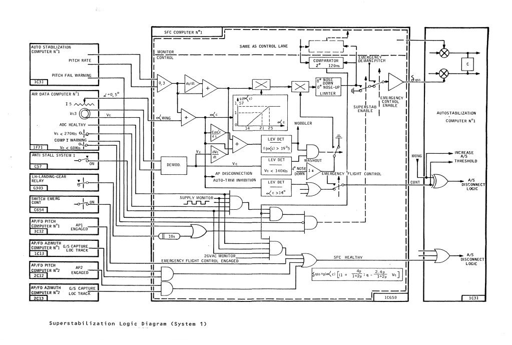
To hopefully further clarify, this was controlled from the SFC computer and was a two part mix:
1) With Vc < 270 KTS the AUTOSTAB pitch damping was increased as a function of pitch rate and pitch rate DOT, Vc DOT and corrected (wing) incidence. Maximum possible demand limited to 8\xb0 nose down.
2) With Vc < 140 KTS and alpha/alpha rate greater than 19.5\xb0 (this itself would generate the 'wobbler' or 'unmistakable warning') a 4\xb0 nose down signal is generated over a 1 second time constant.
I hope the enclosed diagram helps to put it all in place.
Best Regards
Dude

Subjects
Auto-stabilisation
Fuel Burn
Links are to this post in the relevant subject page so that this post can be seen in context.
Reply to this quoting this original post. You need to be logged in. Not available on closed threads.
December 23, 2010, 08:39:00 GMT
permalink Post: 6138966
Best regards
Dude
Subjects
Conversion Course
Fairford
Filton
Links are to this post in the relevant subject page so that this post can be seen in context.
Reply to this quoting this original post. You need to be logged in. Not available on closed threads.
December 23, 2010, 08:54:00 GMT
permalink Post: 6139001
 Yes, of course (as ever
 ) you are correct; it was technically a hybrid system: The servo loops, in terms of ramp and spill door demand signals and resolver position feedback signals etc. DID use conventional analogue drive and servo amplifiers within the AICU, it was the massive arithmetic computation UP-STREAM of these that was digital. I always used to like to refer to the AICS as 'an analog front end with a digital brain'. But that's just me
 .
.
But as you say Clive, none of the control law sophistication (including the synthesising the intake face total pressure and local Mach numbers from mainline aircraft raw air data) would have been possible using analog computation.
Best regards
Dude
Subjects
AICS (Air Intake Control System)
AICU (Air Intake Control Computer)
Intakes
Links are to this post in the relevant subject page so that this post can be seen in context.
Reply to this quoting this original post. You need to be logged in. Not available on closed threads.
December 23, 2010, 09:21:00 GMT
permalink Post: 6139046
Best Regards
Dude
Last edited by M2dude; 23rd December 2010 at 10:42 . Reason: I stil kant sprell
Subjects
Boeing
Nozzles
Pressurisation
Thrust Recuperator
Vortex
Links are to this post in the relevant subject page so that this post can be seen in context.
Reply to this quoting this original post. You need to be logged in. Not available on closed threads.
December 23, 2010, 11:44:00 GMT
permalink Post: 6139267

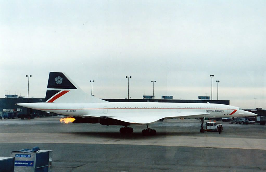
I took this one over the Atlantic, of G-BOAF, BA002 at Mach 2 FL 560 from G-BOAD FL 480 Mach 1.9 (test flight) in July 2003. (Mach 3.9 closing
 ).
).
Best rgards
Dude
Subjects
G-BOAD
G-BOAF
Links are to this post in the relevant subject page so that this post can be seen in context.
Reply to this quoting this original post. You need to be logged in. Not available on closed threads.
December 24, 2010, 11:34:00 GMT
permalink Post: 6141165
Any chance that there was a common discharge point even if the two packs were used alternately?
ChristiaanJ
It seems almost impossible to me that it was 'something' between inner and outer wing, since it would have had to 'jump' over the bathtub covers.
Mike-Bracknell
 ).
).
A very happy Christmas to everyone here; Personally I am working right through Christmas AND New Year (darned aeroplanes)

Dude
Subjects
Nozzles
Pressurisation
Links are to this post in the relevant subject page so that this post can be seen in context.
Reply to this quoting this original post. You need to be logged in. Not available on closed threads.
December 25, 2010, 00:38:00 GMT
permalink Post: 6142224
(I was starting to think that I had gone even more bonkers than usual, and was imagining the things
).
Best regards to all
Dude
Subjects
G-BOAA
Links are to this post in the relevant subject page so that this post can be seen in context.
Reply to this quoting this original post. You need to be logged in. Not available on closed threads.
January 04, 2011, 11:58:00 GMT
permalink Post: 6158425
.
CliveL
Poornamechoice
 (But I am so glad that you are enjoying this wonderful thread).
ChristiaanJ
Speaking for myself, no, it's not a void, it's a highlight, that I now like passing on, in the hope other generations will find inspiration in the 'Concorde Story' for their own endeavours.
).
What is gratifying though, is the enormous amount of interest that there still is for Concorde; both in this thread and in the world at large. I guess she lives on after all.
These pictures of 101 etc are absolutely marvellous; I really like the 'sexy' wing shape photo's. One little unique point about 102; she flew with a different intake control system to any other Concorde, being an 'improved' Ultra Electronics analog system. (Although the intake itself was aerodynamically the same as the later aircraft). Never really understood why our French friends chose this particular path with this aircraft. (Perhaps CliveL can shed some light on this??).
Very best regards to all.
Dude
Last edited by M2dude; 5th January 2011 at 16:54 . Reason: Still can't spell
Subjects
British Airways
Intakes
Nozzles
Thrust Reversers
Links are to this post in the relevant subject page so that this post can be seen in context.
Reply to this quoting this original post. You need to be logged in. Not available on closed threads.
January 07, 2011, 13:13:00 GMT
permalink Post: 6164710
Gentlemen, I think you will find that 102 did indeed have a totally 'unique' analog intake control system. Not only were the RDCUs (not AICUs in this case chaps) totally different, there were major architectural changes over the prototype system too. Also, although the basic intake structure was the same as 101 and all subsequent aircraft, there was still the prototype approach to local pressure sensing adapted, ie. Intake face total pressure P∞ sensed directly via the infamous 'magic holes' rather than using digitally synthesised values based on mainline aircraft manometric probe, total (pitot)pressure. As 101's intakes only went 'live' in mid-march 1973, I assumed that maybe they (AS) wanted an operative intake system from the outset on 102 when it first flew in January of that year. What puzzled me was why they went for this seemingly enhanced (and expensive) analog system on 102 and not the original system. (As 102 used a production type intake, I guess that they would have to have at least made some changes to the control system ; there was no exotic double hinged 'Dump Door', but the far simpler and elegant 'Spill Door' with integral Aux' Inlet Vane that was known and loved by us all). Rumour had it that AS still wanted to pursue the 'magic holes' solution and were dead against the decision to go digital. (This particular decision was taken in October 1970, which makes the 102 AICS route seem all the more strange).
And ChristiaanJ; what you guys achieved with the MAX CLIMB/MAX CRUISE was nothing short of remarkable. Just about the most exotic (and complex) autopilot mode that I've ever seen, that solved so MANY problems.
(Still the only A/P mode I've ever seen where the Autothrottle is engaged in a speed mode at the same time as the AUTOPILOT
).
Best regards
Dude
Last edited by M2dude; 8th January 2011 at 09:58 . Reason: 'All I want for Christmas is the ability to spell'
Subjects
AICS (Air Intake Control System)
AICU (Air Intake Control Computer)
Auto-pilot
Auto-throttle
Intakes
Links are to this post in the relevant subject page so that this post can be seen in context.
Reply to this quoting this original post. You need to be logged in. Not available on closed threads.
January 13, 2011, 09:45:00 GMT
permalink Post: 6176684
Really an answer for CliveL, but I'll have a go. The short answer to your question is 'oh yeah, big time'. Total temperature varies with the SQUARE of Mach number and static temperature. Depending on the height of the tropopause itself as well as other local factors, there can be little or no significant variation of static temperature between FL600 and FL700. The 400\xb0K (127\xb0C) Tmo limit was imposed for reasons of thermal fatigue life, and equates to Mach 2.0 at ISA +5. (Most of the time the lower than ISA +5 static air temperatures kept us well away from Tmo). In a nutshell, flying higher in the stratosphere gains you very little as far as temperature goes. (Even taking into account the very small positive lapse above FL 650 in a standard atmosphere). As far as the MAX SPEED bit goes, Concorde was as we know flown to a maximum of Mach 2.23 on A/C 101, but with the production intake and 'final' AICU N1 limiter law, the maximum achievable Mach number in level flight is about Mach 2.13. (Also theoretically, somewhere between Mach 2.2 and 2.3, the front few intake shocks would be 'pushed' back beyond the lower lip, the resulting flow distortion causing multiple severe and surges).
On C of A renewal test flights (what I always called the 'fun flights') we DID used to do a 'flat' acceleration to Mach 2.1 quite regularly, as part of the test regime, and the aircraft used to take things in her stride beautifully. (And the intakes themselves were totally un-phased by the zero G pushover that we did at FL630). This to me was an absolute TESTAMENT to the designers achievement with this totally astounding aeroplane , and always made me feel quite in awe of chaps such as CliveL.
Shaggy Sheep Driver
So glad you are enjoying the thread, and absolutely loved the description of your flight in OAD and your photo is superb. I don't think it is possible to name a single other arcraft in the world that could be happily flown hands off like this, in a turn with 20\xb0 of bank at Mach 2. (One for you ChristiaanJ; The more observant will notice that we are in MAX CLIMB/MAX CRUISE with the autothrottle cutting in in MACH HOLD. Oh, we are in HDG HOLD too
 ).
).
Now for your question
As far as your air conditioning question goes, you needed an external air conditioning truck to supply cabin air on the ground. Not needed in the hangars of course, but come departure time if these trucks were not working, then the cabin could become very warm/hot place indeed (depending on the time of year). Oh for an APU

Best regards
Dude
Subjects
AICU (Air Intake Control Computer)
APU (Auxiliary Power Unit)
Anti-skid
Auto-throttle
Braking
Depressurisation
Engine surge
FL600
Fatigue
Intakes
Landing Gear
N1 (revolutions)
TMO (Temprature Max Operating)
Links are to this post in the relevant subject page so that this post can be seen in context.
Reply to this quoting this original post. You need to be logged in. Not available on closed threads.
January 14, 2011, 00:06:00 GMT
permalink Post: 6178371
As you say, as the main gear tachos spin up the brakes no longer they think that they are in full skid and can be applied. The only electronic 'protection' as such is the anti-skid itself via that Vo signal in the anti-skid unit (known as the S.P.A.D. box). This would still help control and limit main wheel braking. However the professionalism of my friends such as EXWOK, NW1 and Bellerophon was the REAL protection here. I will let one of them explain the normal braking procedure on landing.
Best regards
Dude
Last edited by M2dude; 14th January 2011 at 00:31 .
Subjects
Anti-skid
Braking
Landing Gear
Links are to this post in the relevant subject page so that this post can be seen in context.
Reply to this quoting this original post. You need to be logged in. Not available on closed threads.
January 14, 2011, 08:00:00 GMT
permalink Post: 6178815
)
Best regards
Dude
Subjects: None
No recorded likes for this post (could be before pprune supported 'likes').Reply to this quoting this original post. You need to be logged in. Not available on closed threads.
January 15, 2011, 08:20:00 GMT
permalink Post: 6180678
I personally agree about that photo, YUCH!!

Now about the cabin pressure thing: The pressurisation system would control to a MAXIMUM differential of 10.7 PSIG. Now at 60,000' the static pressure is 1.04 PSIA and at that altitude we would not QUITE be able to hold a cabin altitude of 6000', more like 6,200-6,300'. This is because 6000' altitude corresponds to a static pressure of 11.78 PSIA, giving us a diff' of 10.76 PSIG. Still as near as dammit mind, and for the MAJORITY of Atlantic crossings 6000' was fine. Such a 'civilised' cabin pressure was just one of the 1000 reasons that you never 'felt' as if you'd just flown over 3000 miles in Concorde.
Here is a diagram of the pressurisation panel.
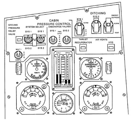
The idea was that you selected a desired cabin altitude and the system would control to maintain that altitude all the way up to max diff. You could control the rate of presurisation too, to minimise popping ears etc. (Personally I always found Concorde particualarly good in that respect). There is one minor goof in the diagram, in that the discharge valve position indicator show both systems in operation. You only ever had one of the two systems in operation (via the SYS1/SYS2 selector switches). The only exception to this was on the ground when both systems were powered (and both sets of valves fully open).
Best regards
Dude
Last edited by M2dude; 15th January 2011 at 08:31 . Reason: kerrektions
Subjects
Pressurisation
Links are to this post in the relevant subject page so that this post can be seen in context.
Reply to this quoting this original post. You need to be logged in. Not available on closed threads.
January 15, 2011, 10:59:00 GMT
permalink Post: 6180912
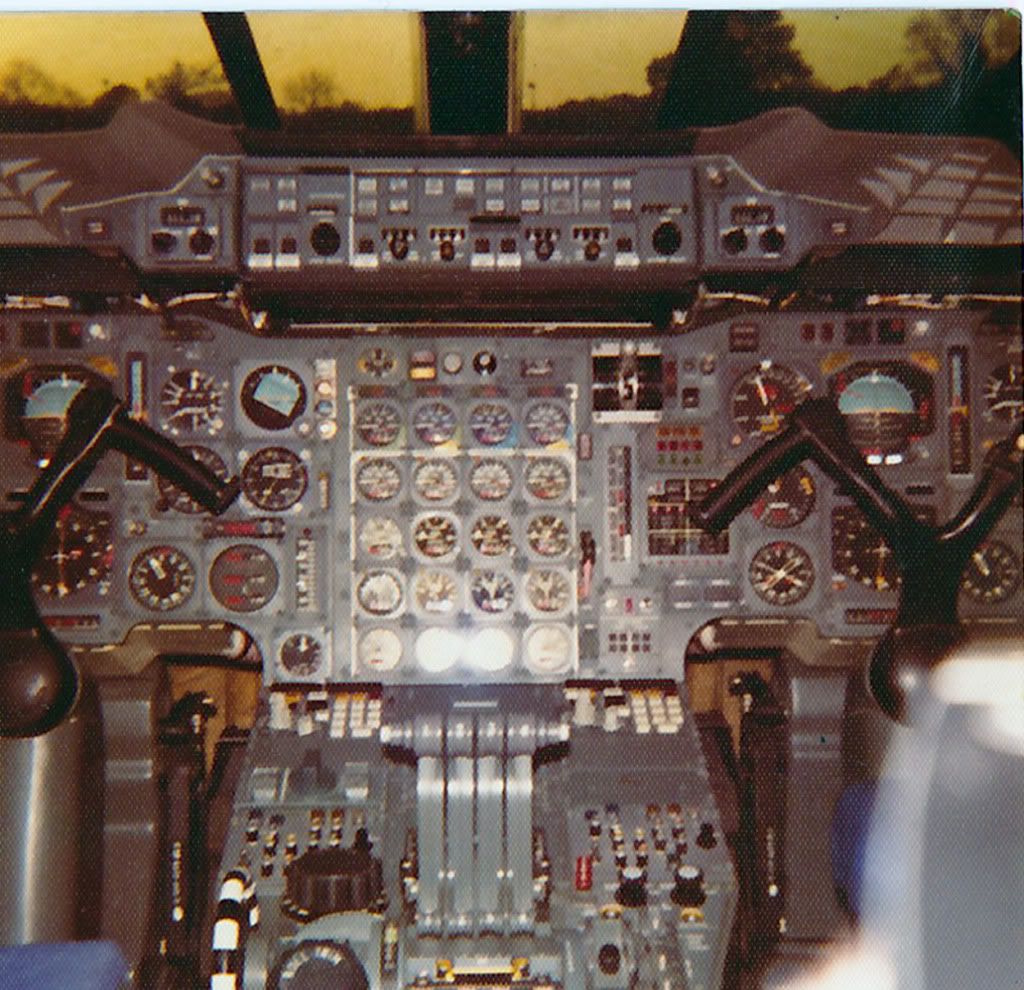
The first thing I know EXWOK and BELLEROPHON will (maybe) notice is that originally OAD had a 'normal colour' electroluminescent light plate on the visor indication panel. (If I remember rightly (it was a million years ago chaps) when this one 'stopped lighting' we could not get a replacement and had to rob 202 (G-BBDG) at Filton; this one being the same black development aircraft colour that OAD has to this day.
The OTHER first thing that you may notice is the Triple Temperature Indicator on the captains dash panel. (The first officer had his in in similar position). These got moved around (twice in the end) when TCAS was installed in the mid-90's. It was amazing just how much equipment got moved around over the years, in order to 'shoe-horn in' various bits of extra equimpent.
The cabin altimeter here fitted just above the #1 INS CDU also got moved (to the centre consul) when the FAA 'Branniff' modifications were embodied later in the 70's. It's spot got occupied by a standy altimeter mandated by the FAA but this was removed after Branniff ceased flying Concorde; the cabin altimeter returning to it's former home. The REALLY observant will notice that there is neither an Autoland Ca3/Cat2 identifier on the AFCS panel (glued on by BA at LHR) or the famous and precision built 'Reheat Capabilty Indicator' flip down plate fitted to the centre dash panel a few years later by BA.
Also not shown here, as they were buyer furnished equipment also fitted at on delivery LHR, are the two ADEUs (Automatic Data Entry Units, or INS Card readers). These were located immediatel aft of the CDU's and were used for bulk waypoint loading ('bulk' being 9, the most that the poor old Delco INU memory could handle). These were removed in the mid 90's when the Navigation Database was fitted to Concorde INUs, and bulk loading then was achieved by simply tapping in a 2 digit code. (Hardly the elegence of FMS, but still very elegent in comparison with the ADEU's, and worked superbly). A little note about these ADEU things; You inserted this rather large optically read paper data card into the thing and the motor would suck the unsuspecting card in. As often as not the ADEU would chew the card up and spit the remnants out, without reading any data, or not even bother spitting out the remnants at all. Removing these things FINALLY when the INUs were modified was absolute joy!!
ps. When G-BOAG (then G-BFKW) was delivered in 1980 it had neither any of the Branniff mods or ADEUs fitted. (Also the INS was not wired for DME updating). This meant that obviously she could not fly IAD-DFW with Branniff but also she could not do LHR-BAH either, because of the lack ADEUs. (You could not manually insert waypoints quick enough over the 'Med', or so the guys told me. So for the first few years good old FKW/OAG just used to plod between LHR and JFK. And plod she did, superbly. She never did get the ADEUs (not necessary thank goodness when the INUs got modified) but we wired in DME updating and so she could navigate around with the best of them.
My gosh I do prattle on, sorry guys.
Best regards
Dude
PS Welcome back Landlady, hope you've recovered from your fall XXXX
Last edited by M2dude; 15th January 2011 at 11:29 .
Subjects
AFCS (Automtic Flight Control System)
Afterburner/Re-heat
Auto-land
British Airways
Cabin Crew
Captains
Fairford
Filton
G-BBDG
G-BFKW
G-BOAD
G-BOAG
INS (Inertial Navigation System)
JFK
LHR
LHR-JFK Route
Visor
Links are to this post in the relevant subject page so that this post can be seen in context.
Reply to this quoting this original post. You need to be logged in. Not available on closed threads.
January 16, 2011, 09:41:00 GMT
permalink Post: 6182606
Hi again my friend. To further expand on CliveJ's superb explanation: Mechanical control inputs were fed to each of the 8 Powerd Flying Control Units (PFCUs), but in electronic signalling (either Blue or Green) these inputs were de-clutched at the PFCU input lever. When Fly By Wire' signalling is not available, the mechanical inputs (which as CliveL quite rightly points out) are driven by the Relay Jacks, now are locked to the input lever and can now move the input jack of the PFCU (known as the spool valve) and subsequently cause the PFCU to drive the control surface. (The body of the PFCU moved, the main jacks were attached at each end to structure and so obviously did not move). Hopefully this diagram will help visualising the process a little easier:
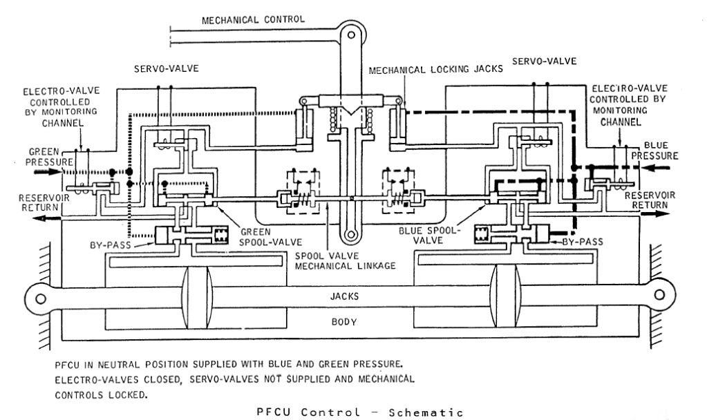
The diagram shows Green & Blue hydraulics supplied but the electro-valves (opened by the respective FBW channel) are both closed. You can see that the mechanical input lever is 'locked' to the PFCU input lever which will drive the SPOOL VALVE directly. When FBW is enabled, either the Blue or Green (never both together) ELECTRO-VALVE are signalled open, the ensuing hydraulic pressure then pushing the input clutch upwards and disengaging the mechanical input. FBW demands are now fed to the respective SERVO VALVE which will hydraulically send the SPOOL VALVE in the desired direction.
The Relay Jacks could be considered to be a little like a PFCU (you had 2 RJs per axix) but instead of the servo valves being driven by the FBW system they were driven by the autopilot and instead of driving a control surface, they drove the control runs. In manual flight the input spool was driven via a mechanical input lever, which would drive the RJ spool a little like Mech' signalling drove the PFCU spool. In A/P mode the mechanical input rod was de-clutched \xe0 la PFCU, but (and here's the clever part) this input was locked to the body of the Relay Jack which when it moved, drove the pilot's control in sympathy. (Control column, yoke or rudder pradals). As the respective control(s) was moved by the Relay Jack, the corresponding FBW position sensor (resolver) would change position and generate the FBW demand. (As the surface moved there was a feedback resolver at PFCU level).
As far as the FBW channels themselves went; there were 2 electronic signalling modes, Blue and Green, sub-divided into 3 groups (Inner Elevons, Outer & Mid Elevons and Rudders). Each group was independently monitored, and a fault in say the Rudder channel alone, would result in the rudders ONLY changing lanes. NOW ( ), The normal control channel was BLUE, and if this failed you would drop the respective channel into GREEN and if this failed you would drop into MECH. The selector switches (1 per group) enabled you to select BLUE/GREEN/MECH in that order. If for some reason you were selected to GREEN, a failure of that signalling lane would not drop you 'up' into BLUE, but into MECH. Your switch would only be in this position if you'd had a problem with BLUE, however you would select this on pushback while you were testing the flying controls, otherwise you spent your whole life selected to BLUE. As far as BA went, I can never remember a time personally when all 3 groups dropped from BLUE to MECH, but very rarely you might get a fault that caused a single group to briefly drop to MECH. Just about one of the very few common mode failures to each of the 3 groups would be a failure of the respective FBW static inverter. This thing, which was rightly monitored up to the hilt, produced a 26 Volt 1800 Hz output. (1800 Hz was chosen as this is not a harmonic of aircraft mainline 400 Hz AC supply)
Best regards
Dude
Last edited by M2dude; 16th January 2011 at 12:10 . Reason: Clarity; Oh for clarity
Subjects
Auto-pilot
British Airways
Elevons
FBW (Fly By Wire)
Hydraulic
Hydraulic System - BLUE
Hydraulic System - GREEN
PFCU (Powered Flying Control Units)
Rudder
Links are to this post in the relevant subject page so that this post can be seen in context.
Reply to this quoting this original post. You need to be logged in. Not available on closed threads.
January 17, 2011, 06:15:00 GMT
permalink Post: 6184321
Ahhh the Tech refresher days.
 Not being an EO it would not have been me, no. But the 'trainers' often used to come seek me out in the hangar and (over coffee, not beer I'm afraid) confer about various system quirks and nasties to use on you guys during the tech' refreshers. (So I guess can be blamed for a few of the 'stinkers', sorry
). And I definately know who you mean by describing him as a 'chatty' EO.... a truly great guy though.
Not being an EO it would not have been me, no. But the 'trainers' often used to come seek me out in the hangar and (over coffee, not beer I'm afraid) confer about various system quirks and nasties to use on you guys during the tech' refreshers. (So I guess can be blamed for a few of the 'stinkers', sorry
). And I definately know who you mean by describing him as a 'chatty' EO.... a truly great guy though.
Mech' signalling during decel'??, OUCH!! I would have thought that the 'supersonic dustbin lid' description would have been quite an accurate description of what must have been a very uncomfortable experience indeed. It was quite a vivid and scary description, I can just imagine trying to move the 3 switches up to BLUE from MECH and stabbing the reset buttons while your seat and the selector panel are seemingly going backwards and forwards, up and down in different directions!!
 . On the C of A renewal test flights I seem to remember that MECH was only tried fairly briefly at a very subsonic 300 KTS during the early stages of the flights, but even then it felt like the aeroplane was riding a sea of different sized golf balls and the outer wing sections seemed to flap about quite enegetically in a world of their own; it was pure bliss when we reset into BLUE. It really shows us all just how good the FBW and autostab really was, the fact that the aeroplane handled so beautifully throughout such an enormous envelope. Well done CliveL and ChristiaanJ and all you designer chaps.
.
. On the C of A renewal test flights I seem to remember that MECH was only tried fairly briefly at a very subsonic 300 KTS during the early stages of the flights, but even then it felt like the aeroplane was riding a sea of different sized golf balls and the outer wing sections seemed to flap about quite enegetically in a world of their own; it was pure bliss when we reset into BLUE. It really shows us all just how good the FBW and autostab really was, the fact that the aeroplane handled so beautifully throughout such an enormous envelope. Well done CliveL and ChristiaanJ and all you designer chaps.
.
Now NW1, I bet you can still really do the flying control check in your sleep (
), but 'Great times, great aircraft, great people' is certainly a marvelous way to sum up such an amazing time of our lives. I still feel honoured and very lucky to have been a small part of it all for so many years.
And as for March... Yes I will be there; see you on the 4th.
Best regards
Dude
Subjects
Auto-stabilisation
FBW (Fly By Wire)
Hydraulic System - BLUE
Links are to this post in the relevant subject page so that this post can be seen in context.
Reply to this quoting this original post. You need to be logged in. Not available on closed threads.
January 18, 2011, 06:28:00 GMT
permalink Post: 6186366
There was no automatic ignition selection logic as such built into the start sequence, but a manually selected L & R ignition selector switch. The reason of course to alternate L & R selection during starting was to detect otherwise dormant ignition failures if 'BOTH' was always selected. (Modern A/C with AUTOSTART do not have this problem, if an ignitor fails during the engine start sequence the other is automatically selected and an ignition status message is set on the lower EICAS screen). The ignition L/R selector switch was bypassed during engine operation by the auto-ignition system, where if the engine control unit detected a flame out (set at 58% N2) both ignitors would automatically fire up. The sequence would release onece the perceived N2 rose above 63%. The ignition system had several reliability issues, the first was the plugs themselves. Penetration into the 'can' was crucial; if it were more than about 130 thou', the tip would very quickly burn off. We soon learned that a penetration check was vital when fitting a plug and shims needed to be used to get the correct penetration. The other reliability issue was the ignition leads themselves; For the first 10 years of service they were a major pain until 'they' (Rolls-Royce) finally got it right. Also until Rolls modified the lead clipping, it could take 3 to 4 HOURS to change a lead. The dual channel HEIU itself was as good as gold, and seldom let us down, It was a very powerful 8 Joule 2KV beast, and you obviously treated it with utmost respect.
Best regards
Dude
Last edited by M2dude; 18th January 2011 at 07:28 .
Subjects
Ignitors
Rolls Royce
Links are to this post in the relevant subject page so that this post can be seen in context.
Reply to this quoting this original post. You need to be logged in. Not available on closed threads.
January 18, 2011, 06:43:00 GMT
permalink Post: 6186380
Since the Brit had some vacuum-driven instruments, there was a test bench in the Filton lab for such instruments. So I brought in my ancient horizon, had it tested.... and it still met the basic specs! They made them well in those days....
 ? HAHAHA).
I seem to remember the Chipmunk used to use a cute little 'vaccy' gyro horizon. I pulled many of these apart during my RAF training. (Sometimes I even managed to get the odd one or two back together and working again).
Best regards
Dude
Subjects
Filton
Links are to this post in the relevant subject page so that this post can be seen in context.
Reply to this quoting this original post. You need to be logged in. Not available on closed threads.
January 18, 2011, 07:15:00 GMT
permalink Post: 6186403
In any case as far as the 'ground engineers' doing the check of the ignitors, in my opinion if you are doing a pre-flight check, there is no point doing it unless it is pre-FLIGHT. Just about every other system on the aircraft got tested right up to when you boys arrived at the aircraft, but quite rightly you tested them again. (The whole point of 'us' testing systems was to pre-empting failures before they could impact the departure time).
Or perhaps you are suggesting that I am hallucinating or worse?
Dude
Last edited by M2dude; 18th January 2011 at 07:27 .
Subjects
Fuel Pumps
Ignitors
Links are to this post in the relevant subject page so that this post can be seen in context.
Reply to this quoting this original post. You need to be logged in. Not available on closed threads.
January 18, 2011, 09:30:00 GMT
permalink Post: 6186581

Clive, you really surprise me when you say you don't think that composites would be used from a future SST, is there a material reason for this? (I'm curious because being of a simple avionic brain, I always assumed composites would be used. But if anyone knows this stuff, you certainly would Clive
).
To answer Mike-Bracknell's original query, as far as avionics goes we can really go to town. For her age Concorde had some truly amazing aircraft systems, for instance the flying controls. To enable mechanical control (both FBW channels failed) there was a highly complex and heavy mixing unit under the rear floor. (To mix pitch and roll pilot mechanical demands into differential elevon demand inputs). This of couse would have to be done away with, as well as the relay jacks and replaced with a pair of side-sticks. (See posts on previous page). A 2 crew operation would obviously be the way to go, but neither desirable or possible in my view when Concorde was designed.
A triplex or quadruplex flying control system (possibly even integrating autoflight) would replace the Concorde collection of several analog boxes with a very small handful of lightweight digital units.. The powerplant control will have major weight savings, just take a look at this lot. 8 Engine Control Units, 4 Bucket Control Units, 2 Nozzle Angle Scheduling Units, 4 Reheat Amplifiers, 8 AICUs, 4 Air Intake Sensor Units and a single Air Intake Test Unit could potentially be replaced by just 4 multi-channel EEC type units. (On subsonic aircraft the EECs are mounted on the engine itself, not sure if that's a good idea for an SST, given the operating environment. Air Data and Navigation systems take a major simplification and weight saving, the 3 INUs and 2 ADCs (All of them straight from the 'rent a hernia' store as far as weight goes), could be replaced by a single ADIRU and a SAARU. The fuel indication/management side of things (2 FQI packs, 2 level switching packs and 3 CG computers) would probably be replaced by a single Fuel Processing unit. Ahhhh perchance to dream
Best regards
Dude
Subjects
ADC (Air Data Computer)
AICU (Air Intake Control Computer)
Afterburner/Re-heat
Avionics
C of G
Elevons
FBW (Fly By Wire)
Intakes
Nozzles
Thrust Reversers
Links are to this post in the relevant subject page so that this post can be seen in context.
Reply to this quoting this original post. You need to be logged in. Not available on closed threads.