August 22, 2010, 01:47:00 GMT
permalink Post: 5884837
So yes, on the whole, TOC did equal TOD.
The 'subsonic climb' wasn't quite as you thought; you'd normally subsonic climb to FL280, staying there (at Mach 0.95) until the acceleration point. Mach 0.95 was 'subsonic cruise'. But you were on the right track.

Oh, and NOPE, they never boomed us either

Nick Thomas
The only problem you ever had with the dual nacelle arrangement was if you had an engine surge above Mach 1.6 (These were relatively rare, but could happen with an engine or intake control system malfuntion). If one engine surged, the other would surge in sympathy, because of the shock system being expelled from one intake severely distorting the airflow into it's neighbour. These surges were loud, quite scary (to the crew that is, most passengers never noticed much), but in themselves did no damage at all. Delicate movement of the throttles (employed during the subsequent surge drill) would invariably restore peace and harmony again to all. (The intake on Concorde was self-starting, so no manual movement of the intake variable surfaces should be needed in this event). After this was over, normal flying was resumed again As I said before, these events were relatively rare, but when they did occur, they would be dealt with smartly and professionally; the engine and intake structure being undamaged. (Post surge inspetion checks were always carried out on the ground after an event, on both engine and intake, but nothing much was EVER found).
Subjects
AFCS (Automtic Flight Control System)
Engine surge
Fuel Burn
G-BOAF
Intakes
JFK
LHR
LHR-JFK Route
LP Compressor
Rolls Royce
Shannon
Vmo
Links are to this post in the relevant subject page so that this post can be seen in context.
Reply to this quoting this original post. You need to be logged in. Not available on closed threads.
August 23, 2010, 08:28:00 GMT
permalink Post: 5886815
Nick Thomas
Last edited by M2dude; 19th January 2011 at 13:42 .
Subjects
Auto-pilot
British Airways
C of G
Fairford
Fuel Burn
G-BOAC
Landing Gear
Mmo
Olympus 593
Rolls Royce
Tail Cone
Tail Skid
Vmo
Links are to this post in the relevant subject page so that this post can be seen in context.
Reply to this quoting this original post. You need to be logged in. Not available on closed threads.
August 24, 2010, 22:49:00 GMT
permalink Post: 5890348
aaah yes, Max Climb/Max Cruise modes. I'd not forgotten this my friend, I was going to say a few words about that in a future post, but maybe we can do that now. (And I'd love to hear more of your comments on this here too, ChristiaanJ). The intake and autopilot modifications were in a way complimentary it's true, but really dealt with separate problems, at least in my view:
The intake control unit software change (a change to the control law that limited engine N1 as a function of intake local Mach number, Mo, and inlet total temperature, T1) was able to put an absolute limit on aircraft achievable Mach number during Mmo overshoots, but it would not PREVENT Mmo overshoots occurring altogether, it was more of a safety brake. This particular overspeed problem manifested itself well before route proving, and in fact the intake system 'fix' resulted in the Thrust Auto Reduce System being deleted, electronic control boxes and all. The TAR system was fitted on all development aircraft equiped with the digital intake system, and it tried (in vain) to limit extreme Mach overshoots. The production aircraft retained the TAR wiring and locked out circuit breakers, as well as two vacant spaces on the electronic racks. The prime reason for all these efforts were that some of the rapid excessive Mach overshoots quite often drove the intake into surge; the modification to this N1 limiter control enabled engine mass flow to be controlled in such a way that these surges could be prevented during temperature shears. The aircraft Mach limit was an extremely useful fringe benefit.
The AFCS mode change from what was Max Op and Max Op Soft (always loved that name) to Max Climb/Max Cruise was at a stroke able to deal with the regular Mmo overspeeds that kept on occuring during, as you say, the route proving trials of 1975, when British aircraft G-BOAC and the French aircrfraft F-BTSD carried out pre entry into service evaluation flights, SD sadly was the aircraft that was tragically lost at Gonez in July 2000). The Max Climb/Max Cruise AFCS mode combo is a mode like no other that I've personally seen before or since anywhere, (it for instance resulted an elsewhere taboo; an autopilot and an autothrotte working together IN A SPEED MODE).
This problem encountered primarily at lower lattitudes, (for example, G-BOAC doing route proving flights out of Singapore), occurring initially as the aircraft reached Mach 2. It was termed 'the insurmountable problem', but the AFCS designers (such as ChristiaanJ) fortunately did not have 'insurmountable problems' in their vocabulary. The issue was that the aircraft would have been climbing rapidly at Vmo of 530 KTS, with throttles at the gate as usual, At exactly 50,189' we hit what was known as 'the corner point' in the flight envelope, where 530 KTS IAS equated to Mach 2 exactly. Max Op mode would then 'let go' of the Vmo segment, and try and control the aircraft to Mach 2. (As the aircraft climbed, Vmo itself would progreesively decrease in order to equate to Mmo, or 2.04 Mach). But in very cold conditions, the aircraft still 'wanting' to accelerate, and the simple Max Op/Max Op Soft modes just could not cope with gentle pitch changes alone. The problem became even bigger during the cruise/climb when severe temperature shears occured, and routinely regular Mmo exceedences occured. Something had to be done, and something WAS done and how; enter Max Climb/Max Cruise. It was really a classic piece of design, where the aircraft would do the initial supersonic climb in Max Climb mode. This mode itself was relatively simple, in that it was more or less a Vmo -Vc hold mode. That meant that the difference at selection between indicated airspeed, Vc and Vmo would be maintained, with a vernier datum adjust to this being available. In practice this mode was selected pretty much at Vmo, so datum adjusting was not always required. Now comes the clever part; the autothrottle, this would operate in standy mode at this point, just waiting there doing nothing, with the throttles at maximum as before. So the aircraft would now climb as Vmo increased to 530 KTS, and then following a now constant Vmo of 530 KTS until the magic 'corner point' (51, 189' remember). Now all hell would break loose; the mode would automatically change to Max Cruise, the autothrottle would also be automaically selected to Mach Hold mode (initially datumed here to Mach 2) and the throttles would retard, attempting to hold this Mach 2 datum, and the autopilot is commands a 'fly up' signal, over a 20 second lag period to 600'/minute. Now comes an even cleverer (?) part; the autothrottle Mach Hold datum is gradually increased over a 100 second period towards Mach 2.02, and so in stable conditions the throttles would now gradually increase again until they once more reach the maximum limit. At this point, the autothrottles now come out of Mach Hold mode and back into the waiting in the wings standby mode. The autopilot would now cancel it's 600' fly up, demand, returning to a datum of Mach 2. There was a little more complexity built in also, where the difference between the 'commanded' and actual vertical speeds offset the autoplilot Mach 2 datum. This would apply whether the autothrottle had cut in (+600'/min demand) or with the throttles back at maximum (0'/minute demand. A positive climb error tweaked the cruise Mach up slightly, a negative error (eg. in a turn) the converse was true. The effect of all of this complexity was that the aircraft itself could 'scan' until it settled at a point where the throttles could be at maximum, and the speed between Mach 2 and 2.02. On the North Atlantic, with warmer ISA temperatures, there was usually just the initial routine with the autothrottle as you hit the corner point. However at lower lattitudes (eg. LHR BGI) there could be a few initial autothrottle intercepts before things settled down. This whole incredible routine completely took care of the insurmountable problem, a problem that was shown not only to be insurmountable, but was put to bed forever, by people like ChristiaanJ.
I hope that my explanation here does not sound too much like gibberish.
EXWOK
I think you've guessed right as far as my identity goes; it's great that it's not just Concorde pilots I can bore the socks off now

PS. I bet the ex-SEOs LOVED your comments

Dude
Last edited by M2dude; 25th August 2010 at 01:14 . Reason: missed out some info' (sorry)
Subjects
AFCS (Automtic Flight Control System)
Auto-pilot
Auto-throttle
Engine surge
F-BTSD
Flight Envelope
G-BOAC
IAS (Indicated Air Speed)
Intakes
LHR
Mmo
N1 (revolutions)
Temperature Shear
Vmo
Links are to this post in the relevant subject page so that this post can be seen in context.
Reply to this quoting this original post. You need to be logged in. Not available on closed threads.
September 05, 2010, 02:29:00 GMT
permalink Post: 5914385
Obviously there are no spoilers, and once you translate to 'vortex lift' (stalled in conventional terms) there is definitely no shortage of drag. (This happened at about 250kts at landing weight).
Supersonic - it was certainly no sailplane and an ability to increase drag wasn't required.
So - there is a bit of the flight envelope where you are subsonic, descending at about 350kts IAS, where you may need a bit of drag; e.g. to make the FL140 limit on the OCK 1A SID (as it then was) to LHR.
To facilitate this, engines 2 and 3 could be selected to reverse idle within certain strict limitations (most of which have now left my brain). The mechanism was to ask the SFE to arm the system on his panel and then to select reverse on the inboards. Where the system was slightly unreliable was that you were running the air-driven buckets with the engines at idle thrust - consequently they sometimes didn't make a full reverse selection, in which case you canx reverse on that engine and managed on one.
Clearly the big event would be if they didn't translate into fwd thrust, which is one of the reasons it wasn't done below 10 000'. I'm not aware of this happening.
To be honest it was only really used when ATC threw an alt constraint at you during the descent, because in general if you just pitched down to 380kts (Vmo when subsonic at typical approach weights) you would get the height off comfortably.
Subjects
Flight Envelope
IAS (Indicated Air Speed)
LHR
Thrust Reversers
Vmo
Vortex
Links are to this post in the relevant subject page so that this post can be seen in context.
Reply to this quoting this original post. You need to be logged in. Not available on closed threads.
September 06, 2010, 09:17:00 GMT
permalink Post: 5916644
Just like Christiaanj I'm trying to dig up an accurate flight envelope diagram. (A lot of my Concorde 'technical library' is out on long term loan), but I would suggest that anywhere within Concorde's published flight envelope you never hit any equivilant to Coffin Corner, a la' U2. The whole issue is really one of air DENSITY, rather that pressure, where as you climb at a given Mach Number, your Indicated airspeed (IAS) falls away with altitude. (Velocity of sound being primarily tied to static air temperature). Now if you are climbing in the stratosphere, where temperature is more or less constant up to around 65,000', you can say that your TRUE Airspeed (TAS) is also constant with climb at a given Mach number. But lift and drag are functions of IAS (the equivalent airspeed that the aircraft would 'feel' at sea level) and not TAS. Because the U2 had a very low Maximum allowable Mach number (Mmo) as IAS fell away with altitude, it would get to the point where it's lowest permitted airspeed (we called this VLA) got to within a few knots of Mmo and severe aerodynamic buffering. i.e. you were screwed with nowhere to go but down
 .
.
In the case of Concorde, Mach 2 at FL500 was 530KTS, falling to 430KTS at FL600. Although we have less lift due to 100KTS lower IAS, the aircraft is now much lighter (this is the whole principal of cruise/climb) which keeps the universe in balance, but drag is now significantly lower too, getting us better MPG
 .
.
On the ASI, the only limitation displayed was Vmo; however the Machmeter did display fwd and aft CG limits at a given Mach number. The ONLY time that Concorde would experience relatively low speeds at altitude was at Top of Descent. I'm a little fuzzy here how it all worked exactly (it's an age thing you know), I'm sure one of the pilots can correct me, but I seem to remember that the autothrottle was disconnected, ALTITUDE HOLD was selected on the AFCS, and the throttles slowly retarded. (If you pulled back too far you'd often get a gentle 'pop surge' from the engines, and you had also to be wary of equipment cooling airflow too). The aircraft was then allowed to gently decelerate, still at TOD altitude, until Mach 1.6, when power was tweaked to give 350KTS IAS and IAS HOLD was selected. The aircraft was now free to carry out her loooong descent to 'normal' altitudes. VLA on Concorde was not directly displayed as you never flew anywhere near it, and also every pilot knew his VLA
. (Stray into this and you'd get a 'stick' shaker warning.
I hope this blurb helps Nick
Dude
Subjects
AFCS (Automtic Flight Control System)
Auto-throttle
C of G
Engine surge
FL600
Flight Envelope
IAS (Indicated Air Speed)
Lift Drag Ratio
Mmo
Stick Shaker
TAS (True Air Speed)
Vmo
Links are to this post in the relevant subject page so that this post can be seen in context.
Reply to this quoting this original post. You need to be logged in. Not available on closed threads.
September 20, 2010, 16:18:00 GMT
permalink Post: 5945693
In case it's of interest (and suitable health warning as the memory fades)...
The heat did evaporate water vapour in the airframe - reducing corrosion. I remember when the 5 BA aircraft were returned to service, after the post-accident mods, their weight and balance certificates were prepared and found to be out by (IIRC) more than a tonne. This represented water in the airframe present after a year on the ground, and was gone again after a couple hours of supercruise on return to service. Back to the weighbridge for new W&B Certificates....
Vortex lift caused buffet which felt very similar to a conventional wing's stall/low speed buffet. At landing weights (I hate the trend of using the term "mass": weight is a force, mass is not!) you felt the buffet start as you reduced speed (CAS: Vc) to about 250kts. It was handy as a reminder that you should select visor down / nose to five below 250kts (the recommendation was as you slowed through 270kts, but latterly we were in the habit of holding at 250kts nose/visor up - I think TCAS was quoted as a backup to the more limited visibility in that config). At takeoff weights, the buffet went at more like 270kts accelerating. So I'm pretty sure there was no vortex lift at AoA > 7 degrees (250kts at LW).
Recommended subsonic cruise at MTOW was F260 / M0.95 which was equal to Vmo of 400kts (CAS). It was best cruise because Vc=400kts was also min drag at MTOW. F280 meant a slightly more draggy speed of 384kts, but some preferred it because when cleared to climb & accelerate supersonic (the official expression was "go for it") it gave you a bit of slack against Vmo when eng put the reheats in. But we tended to ignore the overspeed warning anyway: it was supposed to go really really fast...
We never flew with visor down and nose up unless it was bust - that config was only used during pushback (except one captain who always thought it looked better visor up....). Visor down max Vc was 325kts/M0.8 so it would limit subsonic cruise, and besides it made a racket like that.
It was a beaut in x-winds - a total lack of yaw-roll couple meant you just straightened the 'plane up with rudder and carried on into the flare as normal. No roll to counteract, and the sideways "lift" created by the rudder deflection on the fin pretty much equalled the x-wind drift. Nice.
Wind limits were Crosswind 30kts (15kts contaminated or autoland), Headwind for autoland 25kts (or manual "reduced noise" approach: that's a technical way we used to reduce the noise footprint down to 800' by flying at 190kts then reducing to a target speed of Vref+7kts at that point). Tailwind 10kts. All these limits were, of course, subject to "on the day" performance limits calculated at the time. I seem to remember there was an over-arching limit of 6000' on r/w length, subject again to "on the day" performance limits. OK, I cheated on this paragraph and dug out FM Vol 2a.
There were loads of other limitations which were, by and large, more "esoteric" than a conventional airliner and which had to be learned for the conversion course. It really made the head hurt, and would have been impossible without a big loverrly picture of the beast on the wall chucking out yellow smoke and making noise. Even a static picture of her seemed to make noise...
No one who flew it could really believe their luck, but one thing for sure is "they don't build them like that any more"...
Ahhhhhhhhhhhhhh..........
Subjects
Afterburner/Re-heat
AoA
Auto-land
British Airways
Captains
Conversion Course
Corrosion
Rudder
Super-cruise
Visor
Vmo
Vortex
Links are to this post in the relevant subject page so that this post can be seen in context.
Reply to this quoting this original post. You need to be logged in. Not available on closed threads.
November 03, 2010, 04:17:00 GMT
permalink Post: 6034995
It was a balancing act and different for each departure - the RoC actually went up the faster you went so you were easing up, maximising the acceleration, while ensuring you (just) made the SID alt requirements.
So, apart from a few seconds holding 250kts, there really wasn't a mode that would work in pitch; you would have to take vert speed and be constantly asking the NHP to select different VS's and HDGs and they had quite enough to do already. No benefit, so don't use it.
Once you'd got to Vmo during the SID (it was 400kts at that point) you could use Max Climb mode (see earlier discussions) and that was generally when the FD was engaged.
It was permissable to engage the AP at an early stage, in which case HDG mode and Pitch Hold would be used, but it was more effort than hand-flying, less accurate and less fun so that was a rare event.
On approach, if an ILS was being flown, you are correct that the FD could be used, although for a typical approach it needed to be off at 300'. This was because wherever possible we flew a 'Reduced Noise Approach' (again, see earlier comments) which consisted of holding 190kts to 800' then reducing to final speed to be stable by 300'. AP/FD had to out by 300' in this case, owing to the very tight pitch control required for which it wasn't certificated (although it could carry out a very good coupled approach and landing if given a more stable approach).
In summary - a very 'hands-on' aeroplane. And all the better for it

Subjects
Noise Abatement
Vmo
Links are to this post in the relevant subject page so that this post can be seen in context.
Reply to this quoting this original post. You need to be logged in. Not available on closed threads.
December 21, 2010, 11:19:00 GMT
permalink Post: 6135263
It is a little complicated, but let me go back half a step.
Concorde was not certificated to FARs or BCAR (the French code was essentially a straight translation of FAR) but to completely new set of requirements known as TSS (Transport Supersonique Standards). The old UK ARB had initiated discussions about these even before cooperation negotiations had started. The result was that young, junior engineers got to debate the basics of airworthiness rules with older, experienced airworthiness specialists. In hindsight it was wonderful training!
But to get to the point, it was this thinking that allowed us to ignore some of the older rules which, although great for the aircraft flying at the time they were written, had little or no relevance to SSTs. We could interpret that as trying to find out what the pilots really wanted the aircraft to do and then to try and provide it.
In the particular case of trim/speed stability it was quite clear that what they wanted was an aircraft that could be flown with minimal trim changes and which once trimmed would not go wandering off all over the place. We also knew that in some cases the 'elevator angle per 'g' ' could get as low as one degree/g in some cases and that the pilot could not tell exactly where his hands were positioned to that precision, although he would always know if he was pushing or pulling. So we could abandon the old rules for stick movement and instead supply classic stick force stability for deviations from the trimmed state.
All this had to be matched to the varying aerodynamics through the transonic region (where everything varies rapidly) and the fuel transfer system characteristics. The resulting Mach trim laws were quite complex and were not, in fact just Mach Number sensitive. We also had two airspeed (Vcas) terms, one of which had a variable gain which was itself Mach dependent and kicked in above Vmo = 5kts and the other was a straight nose up elevator command as a function of Vcas. The Mach trim itself was highly nonlinear. The best way to illustrate this is probably a diagram but now I've run into another gap in my knowledge of this thread - how do I do that?
Anyway, the result was that the fuel transfer held the trim setting variation down to between 2 deg down to 1.5 deg up through the acceleration from 0.95M up to 0.5 deg down at Mach 2.0. Without fuel transfer the trim at Mach 2 would have been closer to 10 deg. The trim between say 0.95 and 1.2 varies in a nonlinear fashion and the Mach trim law shows roughly similar variations.
But the best measure of our success is the comments we are getting here from the guys who actually had to fly it.
Clive
[IMG]file:///C:/Users/Clive/AppData/Local/Temp/moz-screenshot.png[/IMG][IMG]file:///C:/Users/Clive/AppData/Local/Temp/moz-screenshot-1.png[/IMG]
Subjects
Auto-trim
Mach Trim
Trim
Vmo
Links are to this post in the relevant subject page so that this post can be seen in context.
Reply to this quoting this original post. You need to be logged in. Not available on closed threads.
December 26, 2010, 15:58:00 GMT
permalink Post: 6143964
Mike's earlier question had me scratching my head too, hence my question.
What are the fundamental reasons for each of the limitations, and what were the consequences of going outside them?
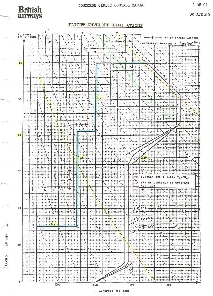
Going clockwise from the left, we have :
VLA (lowest admissible speed)
One would expect a curve for constant alpha max against IAS and altitude, not the staircase in the diagram.
Was this for simplicity of use of the diagram?
Max altitude (60,000ft)
This is the 'simplest' one: it was the highest 'safe' altitude from which an emergency descent could be made, in the case of a window blowing out, without having the blood of the pax boil....
Test flights (without pax, and with the crew pressure-breathing oxygen) did go as high as 69,000ft.
Mmo (max operating Mach number)
Mach 2.04 is usually quoted as having been chosen to assure an adequate life of the airframe.
But what effect does a higher Mach number as such have?
Or are Mmo and Tmo (127\xb0C) directly related?
Vmo (max operating speed) = 530kts until 43,000ft
I suppose this is related to structural limits (qmax)?
Vmo reducing to 380/400kts at about 33,000ft
What is the limiting factor here (other than qmax)?
Vmo constant at 380/400kts down to 5,000ft
What is the limiting factor here? The answer will no doubt also explain why this is slightly weight-dependent.
Vmo reducing to 300kts between 5,000ft and 0 ft
Why the sudden change below 5,000ft?
CJ
Subjects
Depressurisation
Flight Envelope
IAS (Indicated Air Speed)
Mmo
TMO (Temprature Max Operating)
Vmo
Links are to this post in the relevant subject page so that this post can be seen in context.
Reply to this quoting this original post. You need to be logged in. Not available on closed threads.
December 26, 2010, 18:47:00 GMT
permalink Post: 6144161
One would expect a curve for constant alpha max against IAS and altitude, not the staircase in the diagram.
Was this for simplicity of use of the diagram?[quote]
I don't have a complete explanation for all the regions - it was a long time ago and I'll need to dig, but:
Below 16000 ft Vla obviously needs to go as low as Vref to cover landing at elevated airfield altitudes. At present I don't have a satisfactory explanation for 250 kts between 16000 ft and about 45000 ft (250kts/Mach 1.0) A constant value in IAS is what you would get for a constant CLmax (the alphamax is not really the driver). Vla should give a margin above stall, and a quick sum suggests that 250 kts would be consistent with a 1.3Vs condition and a CLmax of about 0.8 up to Mach 1.0, which is not unreasonable, but I am not saying that is the correct interpretation.
From 45000 ft to 60,000 ft I think Vla may be set by manoeuvre requirements. Certainly the forward CG envelope boundary between 1.0M and 1.5M discussed in earlier posts is very close to the requirement to be able to pull 1.2g with half hinge moment available at Vla and heavy weights. Again not certain, but best guess at the moment.
This is the 'simplest' one: it was the highest 'safe' altitude from which an emergency descent could be made, in the case of a window blowing out, without having the blood of the pax boil....
Test flights (without pax, and with the crew pressure-breathing oxygen) did go as high as 69,000ft.
[quote ]Mmo (max operating Mach number)
Mach 2.04 is usually quoted as having been chosen to assure an adequate life of the airframe.
But what effect does a higher Mach number as such have?
Or are Mmo and Tmo (127\xb0C) directly related?[quote]
I have always been puzzled by this statement as one does not normally associate Mach Number with a life limit. Going through my collection of lectures I found another, more plausible explanation:
quote" The scheduled cruise mach Number was 2.0. associated with a structural total temperature of 400 degK. Above ISA +5 Mc was cut back to maintain 400 degK.
To cope with variations of flight mach Number about Mc associated with often rapid and significant changes in wind and temperature which occur particularly in the vicinity of the tropopause (which can of course be as high as 60,000 ft in the tropics) a maximum operating Mach Number (Mmo) of 2.04 is selected" unquote [Leynaert, Collard and Brown, AGARD Flight Mechanics Symposium October 1983]
This is much more in line with my memory on this subject.
I suppose this is related to structural limits (qmax)?
What is the limiting factor here (other than qmax)?
What is the limiting factor here? The answer will no doubt also explain why this is slightly weight-dependent.
Why the sudden change below 5,000ft?
a) there is absolutely no advantage is having a high Vmo at low altitudes as it could not be exploited even if one wanted to because of ATC limitations to 250 kts below 10,000 ft (in the USA at least)
b) there are a lot of things that get rapidly worse if you encounter them at high speed and which are anyway more likely at low altitude - hail, birds etc.
So why store up trouble for yourself!
CliveL
Subjects
C of G
Depressurisation
IAS (Indicated Air Speed)
Mmo
TMO (Temprature Max Operating)
Vmo
Vref
Links are to this post in the relevant subject page so that this post can be seen in context.
Reply to this quoting this original post. You need to be logged in. Not available on closed threads.
April 24, 2011, 14:09:00 GMT
permalink Post: 6409591
I would have thought that the whole venture was a proof of concept by SFENA for future implementation in the Airbus family. This excersise would have been both costly and highly complex at system level, any other reason would really have been quite daft.
Best Regards
Dude
Last edited by M2dude; 24th April 2011 at 15:08 .
Subjects
Airbus
Auto-stabilisation
Elevons
Fuel Burn
Sidestick
Vmo
Links are to this post in the relevant subject page so that this post can be seen in context.
Reply to this quoting this original post. You need to be logged in. Not available on closed threads.
April 25, 2011, 06:54:00 GMT
permalink Post: 6410658
 As we do not know what the PROPOSED flight regime was, on the part of SFENA and Aerospatiale,we also can not assume that any particular manoeuvr would not have been considered. (But as I said before, it would be great to find out the whole story).
The limited authority for roll autostabilisation (and hence Emergency Flight Control) was of course a very deliberate piece of design. (You could test the Emergency Pilot on the ground at ADC Test 2 (Which simulated several seperate overspeeds, including Vmo +20) and when you put in a roll demand (against some resistance), only the MIDDLE elevons deflected. It really looked wierd on the ICOVOL as well as outside the aircraft.
(To any chaps or chapesses who are not aware, above Vmo+20 KCAS, a system known as OUTER ELEVON NEUTRALISATION was invoked, where any input demand to the outer elevons was met by an automatic equal and OPPOSITE input, that of course completely neutralised the demand, giving a zero OUTER elevon deflection).
Best regards
Dude
Subjects
ADC (Air Data Computer)
Elevons
Vmo
Links are to this post in the relevant subject page so that this post can be seen in context.
Reply to this quoting this original post. You need to be logged in. Not available on closed threads.
June 24, 2011, 00:15:00 GMT
permalink Post: 6532637
<<No, I meant the airspeed you'd be flying at while climbing (post takeoff)>>
OK, then the answer to your Q's:
Also what was the typical climb speed
- At lift-off? About 200kts
- Once 240 kts is achieved? 240kts
- At minimum maneuvering speed at typical takeoff weight? Vla after takeoff was V2 until 15,000'. I.E. about 220kts
- At MTOGW? V2 didn't vary much by weight
Out of JFK we flew at Vmo once further than 12nms from the coast. Vmo=400kts IAS at low level.
Out of LHR overland the IAS restriction was 300kts until past the speed limit point early in the SID - much less draggy than 250kts and hence better climb rates. But you'd quickly be released to get to 400kts (barder's pole) where it was designed to be flown.
<<Why higher speed? That have to do with shockwaves and the resulting pressure distribution differences?>>
The flight envelope was bigger and more complex than subsonic types: it was developed in flight test and probably had many considerations involved. I think someone posted it earlier in this thread in graphical form (from the flight manual) if you want to see it. In practice, you had to be aware of three basic parameters - IAS, Mach and CG position (the CG "corridor"). Once understood, it wasn't that difficult to keep up with it...and the IAS and Machmeters had barber's poles handily programmed to show the limiting values (including, cleverly, max temp on the nose Tmo=127 degrees celcius).
Regarding climb rates - best ROC was at 400kts (MTOW) or 380kts (MLW). As speed reduced below that, drag increased and ROC reduced. At MTOW and 400kts you'd get about 4000fpm max dry power. At 250kts it was all noise and very few feet per minute - after noise abate procedures you had to lower the nose, just barely climb, and get IAS up toward min drag as soon as possible. With an engine failed go for 300kts minimum - Vmo as soon as you can.
<<shockwaves and the resulting pressure distribution differences>>
You had to avoid the "transonic" region due to these effects: maximum subsonic cruise was 0.95M due to the auto-stabilised flying controls become over-active as shockwaves started to "dance" around the airframe (usually asymmetrically). This calmed down by about 1.3M in the acceleration (when the intake ramps started to do their thing). To accelerate to 2.0M you needed reheat until 1.7M so you didn't hang around between 0.95M and 1.7M. FL260 was best for subsonic cruise because at that level 400kts IAS = 0.95M...
Last edited by NW1; 24th June 2011 at 09:09 .
Subjects
Afterburner/Re-heat
C of G
Flight Envelope
IAS (Indicated Air Speed)
Intakes
JFK
LHR
Shockwave
V2
Vmo
Links are to this post in the relevant subject page so that this post can be seen in context.
Reply to this quoting this original post. You need to be logged in. Not available on closed threads.
April 06, 2012, 19:42:00 GMT
permalink Post: 7121591
SORRY - senior moment - this should have been posted on another thread!

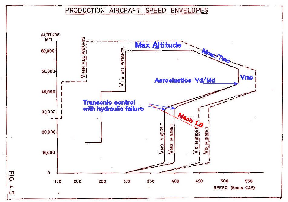
To be honest I can't remember exactly why 530 kts was chosen for the supersonic Vmo, but it was probably the best climb speed.
Mmo/Tmo was limited by a combination of intake and structural temperature.
The 'cut-off' in the sloping/530 kts boundary was, if I remember correctly, to avoid a minor aeroelastic problem at the Vd/Md condition one arrived at from that corner.
The variation of Vmo with weight was a device which, when associated with the CG corridor, allowed the aircraft to meet the manoeuvre requirements when flying on half hydraulics.
400 kts CAS gave 0.93M at around 28000 ft if I recall correctly, which was just below drag rise and gave optimum subsonic cruise performance
Last edited by Jetdriver; 21st April 2012 at 00:33 .
Subjects
C of G
Intakes
Vmo
Links are to this post in the relevant subject page so that this post can be seen in context.
Reply to this quoting this original post. You need to be logged in. Not available on closed threads.
April 22, 2015, 11:59:00 GMT
permalink Post: 8952053
Meanwhile, I await the truth as you do Octane, from our resident experts, to whom I offer warm thanks and have the greatest admiration!
Subjects
Vmo
Links are to this post in the relevant subject page so that this post can be seen in context.
Reply to this quoting this original post. You need to be logged in. Not available on closed threads.
April 22, 2015, 14:52:00 GMT
permalink Post: 8952197
VAPILOT is spot on regarding the reasons for Vmo, of course.
Doesn't answer your 'during flight testing' question, I concede. Sorry!
Subjects
Vmo
Links are to this post in the relevant subject page so that this post can be seen in context.
Reply to this quoting this original post. You need to be logged in. Not available on closed threads.
April 22, 2015, 16:26:00 GMT
permalink Post: 8952291
Tmo was a long exposure structural limit
Mmo was an intake limit
Vmo was a structural (flutter) limit
Subjects
Intakes
Mmo
TMO (Temprature Max Operating)
Vmo
Links are to this post in the relevant subject page so that this post can be seen in context.
Reply to this quoting this original post. You need to be logged in. Not available on closed threads.
April 23, 2015, 08:09:00 GMT
permalink Post: 8952860
To be clear, the original question related to maximum speed which I took to be Vd - 455 kts from about FL 60 up to about FL 360
This was the flutter clearance and was usually acheived in a dive. Vmo was thenwhat you got by backing off to give the statutory margins. Not strictly a flutter limit though limited by flutter! Vmo of course could be flown dry
Subjects
Vd
Vmo
Links are to this post in the relevant subject page so that this post can be seen in context.
Reply to this quoting this original post. You need to be logged in. Not available on closed threads.
April 28, 2017, 17:40:00 GMT
permalink Post: 9755281
See section 4 on this web page: Heritage Concorde
On the extreme right - microscopic explanatory type (sorry!)
Since one of its triggering events is a loss of electrical power, the red flag will be showing unless the aircraft electrical system is powered up (my guess). So it shows red in most cockpit photos.
Subjects
Barber Pole
Vmo
Links are to this post in the relevant subject page so that this post can be seen in context.
Reply to this quoting this original post. You need to be logged in. Not available on closed threads.