June 01, 2012, 18:34:00 GMT
permalink Post: 7221513
Subjects
Vortex
Links are to this post in the relevant subject page so that this post can be seen in context.
Reply to this quoting this original post. You need to be logged in. Not available on closed threads.
August 04, 2012, 11:43:00 GMT
permalink Post: 7341902
I don't think there is any published explanation, but maybe this will help.
Basically the problem with #4 intake was that it was on the RHS of the airplane. We are talking about low speed right? and especially zero forward speed when the engine is trying to suck as much air as it can get from wherever it can get it. That means that the induced angle of attack on all the intake leading edges is going to be high.
The best drawing I can find that shows the flow into the right hand pair is this
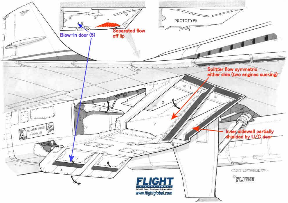
The intake leading edges were all sharp, so the flow would separate if subjected to a high AoA. The upper lip was protected a little by the wing leading edge, and we were obliged to modify the prototype LE ahead of the intakes to prevent underwing vortices developing at low AoA in cruise which also helped a bit.
The lower lip had a substantial separated flow 'bubble' at low forward speed as shown in red, but this cleared up quite quickly as the aircraft gathered speed. It was'cured' by the blow-in doors.
The inner sidewalls were shielded by the landing gear doors, so the AoAs on the sidewall on that side were quite modest.
The splitter was of course subject to equal flow demands on either side so the flow over that was pretty well symmetric.
That leaves the two outer sidewalls which, look for all the world like highly swept delta wings with sharp LEs mounted vertically.
Like all such wings when operated at high AoA they develop powerful vortices on the 'leeward' side. Looking back towards the engine the vortex on #4 engine was anticlockwise and that on #1 was clockwise. [Hope I got that one the right way round
 ]
]
The OL593 rotates clockwise looking aft so the induced incremental AoA on the compressor blades was different on #1 and #4. The difference was enough to trigger some mild blade vibration - hence the rpm restriction until the intake capture was good enough to reduce the vortex strength.
Subjects
AoA
Intakes
Landing Gear
Vortex
Links are to this post in the relevant subject page so that this post can be seen in context.
Reply to this quoting this original post. You need to be logged in. Not available on closed threads.
September 02, 2012, 12:06:00 GMT
permalink Post: 7391887
Subjects
Vortex
Links are to this post in the relevant subject page so that this post can be seen in context.
Reply to this quoting this original post. You need to be logged in. Not available on closed threads.
October 14, 2013, 15:06:00 GMT
permalink Post: 8098479
ref heritageconcorde.com
Does anyone have any details on the 'joint' development alluded to above?

The problem apparently was that flame stabilisation operating in "contingency" rating was sensitive to the point that every engine had to be checked, so there was a lot of engine plus reheat testing, most of which was done at Patchway. The solution was addition of some form of 'spike' at various points on the spray bar (my informant wasn't very specific). It sounded like a sort of vortex generator cum chine that gave the flame somewhere to latch onto. The development process was, as you suggested, a joint activity.
Subjects
Afterburner/Re-heat
Rolls Royce
Vortex
Links are to this post in the relevant subject page so that this post can be seen in context.
Reply to this quoting this original post. You need to be logged in. Not available on closed threads.
February 04, 2017, 08:26:00 GMT
permalink Post: 9664255
Most of the lift is generated on the upper surface and is dominated by the vortex lift which is a product of vortex strength and airspeed. The vortex strength depends on the local aoa at the leading edge. As the aircraft enters ground effect the passage of air under the wing is restricted so more has to go over the top and the local LE aoa is increased along with vortex strength. The important bit of the wing for this bit of lift increase is the front half which is in the higher part of the wind profile. But in any case, following our old friend Bernoulli, the upper surface suction will depend on the resultant circumferential velocity as the vortex scrubs its way across the wing upper surface, and I can't see a knot or two of wind making a big difference to the circumferential velocities under those vortices.
The undersurface flow is of course restricted. and the lift is more Newtonian in character. A reduction in local airspeed because of the wind height profile could give a reduction in lift due to ground effect near the TE. However, in the normal course of events this additional lift is accompanied by a nose down pitch which is countered by a steadily increasing back stick movement as the pilor maintains the more or less constant pitch attitude "flare" manoeuvre. This up elevator gives an increasing negative lift to maintain pitch control which, since the effective cop of the elevator lift is at the elevon hinge line means that the net gain in overall lift from this part of the ground effect is quite small. If this undersurface TE lift were to be reduced by the wind gradient the effect would. be that the nose down pitch would be smaller than usual and the pilot would have to apply less back stick, but I doubt he would notice this in a dynamic situation (remembering that strong winds are usually accompanied by turbulence).
So I can't identify any gremlin job specification that might support n5296s's argument.
Kaypam: Remember the Concotrde was certificated to TSS Standards not JAR25. The certificated approach speed is Vref, Vref plus 7 if memory serves, was introduced as an approach noise reduction and became anaccepted norm so Vrefplus 10 should be OK for 20 kt winds?
Last edited by CliveL; 4th February 2017 at 09:30 .
Subjects
AoA
Elevons
Vortex
Vref
Links are to this post in the relevant subject page so that this post can be seen in context.
Reply to this quoting this original post. You need to be logged in. Not available on closed threads.
January 22, 2020, 16:26:00 GMT
permalink Post: 10668831
Finally as promised, here is a schematic of the AFT part of the fuel vent system. As you can tsee the fin intake pressurises the air space above tank 11, and hence, via the Scavenge Tank air-space, the remaining tanks. (Also you can see the Trim Pipe Drain Vaves you were asking about.
Regards Dude
hi! I know I may be super late to the party here, wondering if you have another picture of that fuel vent schematic? I can\x92t seem to see that one, maybe it\x92s been too long. Anyway it\x92d be much appreciated. Thank you!
Subjects
Fuel Vent System
Intakes
Trim
Vortex
Links are to this post in the relevant subject page so that this post can be seen in context.
Reply to this quoting this original post. You need to be logged in. Not available on closed threads.